0
\$\begingroup\$

I'm an electronics hobbyist struggling with the concept of transistors. I made a simple circuit with a PNP transistor based off of a diagram, but don't understand how it works.

From the book containing the diagram:

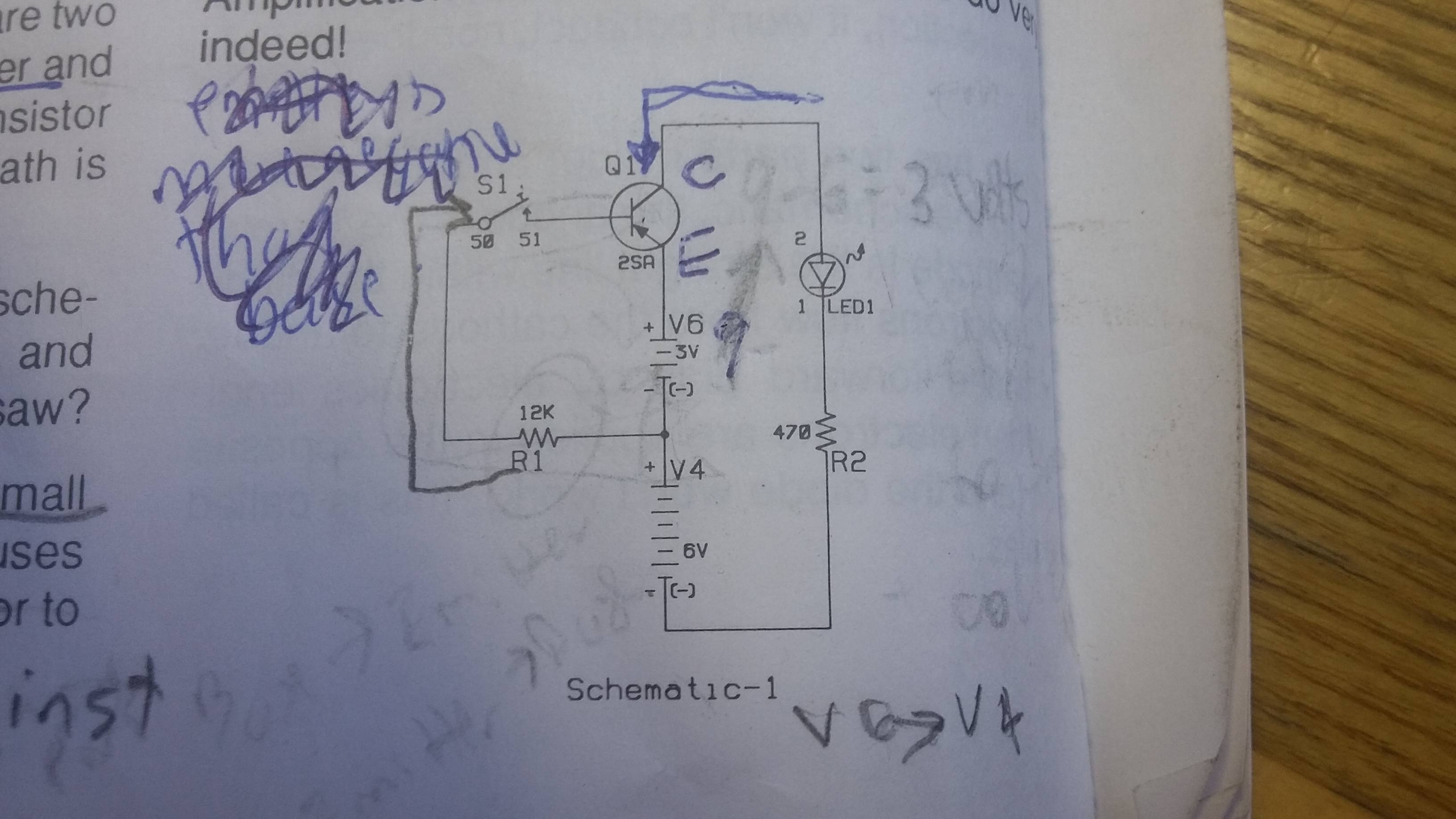
Look carefully at schematic I. You see there are two paths for the current: one from base to emitter and another from the collector to emitter. The transistor is a PNP type. Notice the base to emitter path is open until you press the key.

enter image description here

What I dont get is the direction of current flow. I read that current has to flow against the direction of the arrow, but looking at the circuit, how could the LED light up if electrons can only pass the other direction? (opposite the blue arrow?)

Also I would really appreciate an explanation of the values for power sources (3V and 6V); On the board, V6 is 9 Volts while v4 is 6 volts so I'm unclear how they arrived at those values. Really appreciate your help; I've spent hours researching this and still am baffled.

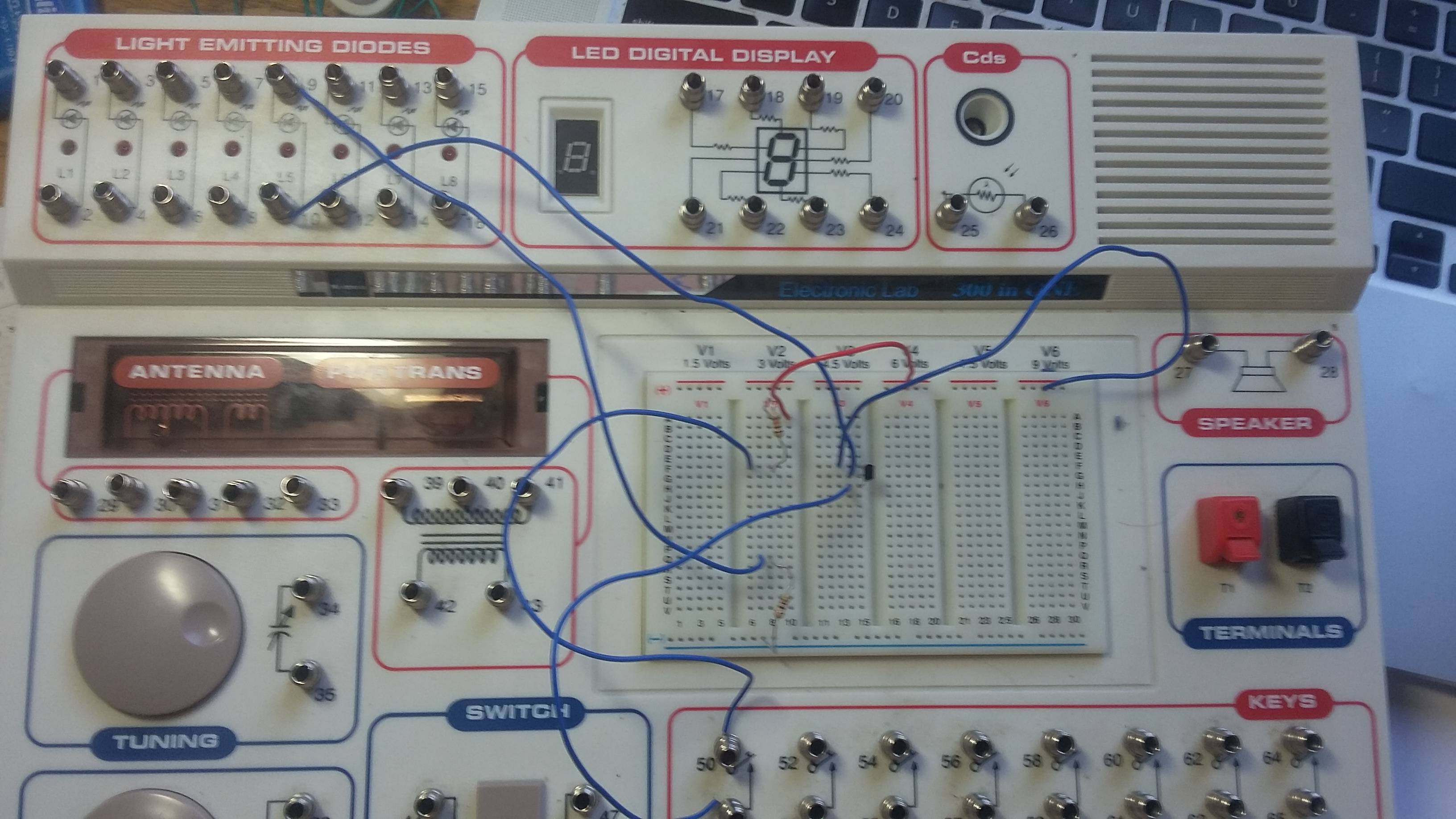
Here's a picture of my circuit board:

enter image description here

\$\endgroup\$
2
  • 1
    \$\begingroup\$ Throw away that book and get a better one. That schematic is drawn with no regard for the normal conventions of schematics, making it very confusing to read. \$\endgroup\$
    – The Photon
    Commented Jul 11, 2017 at 1:47
  • \$\begingroup\$ Related: Which way to draw diode in a circuit diagram \$\endgroup\$
    – The Photon
    Commented Jul 11, 2017 at 1:55

2 Answers 2

2
\$\begingroup\$

What I dont get is the direction of current flow. I read that current has to flow against the direction of the arrow, but looking at the circuit, how could the LED light up if electrons can only pass the other direction? (opposite the blue arrow?)

You are confusing conventional current flow and electron flow. In this circuit, when the switch is closed, electrons flow will be in the direction of your blue arrow, meaning that conventional current will be flowing opposite the direction of the arrow, exactly as required to light the LED.

Probably your book is trying to teach things in terms of electron flow rather than conventional current flow. In any case, they have drawn their schematic with entirely different conventions than the rest of the world uses. Throw that book away and get one that will teach electronics in a way that will allow you to communicate with other electronics hobbyists and electrical engineers.

\$\endgroup\$
2
\$\begingroup\$

"Conventional Current", used by most scientists, engineers and technicians, is a flow of positive charges, from the positive terminal of the battery, through the external circuit, and returning to the negative terminal of the battery. The arrow in transistor and diode symbols (except Zener diodes) points in the direction of conventional current flow.

You apparently are used to electron (negative) current - this concept was apparently introduced to teach technicians how vacuum tubes work, as it is very difficult to explain vacuum tube operation using conventional current. You should try to get used to using conventional current, as most people use that concept.

The circuit in your question is drawn in a very confusing manner - try re-drawing it with the most positive voltage at the top, and most negative at the bottom of the drawing - it may make more sense drawn that way.

\$\endgroup\$

Your Answer

By clicking “Post Your Answer”, you agree to our terms of service and acknowledge you have read our privacy policy.

Not the answer you're looking for? Browse other questions tagged or ask your own question.