1
\$\begingroup\$

I have a system that consists of 1 Arduino, 1 Raspberry-pi, 2 power banks, and a set of different sensors. Each of the Arduino and Raspberry-pi is powered by a separate power bank. I need an accurate method to measure the total power consumed by the entire system.

I also need this power measurement as feedback input to the Arduino to control some sensors. Is it better to tap some power measurement circuit on each power bank or is there a better way to measure it by Arduino/Raspberry-pi.

\$\endgroup\$
2
  • \$\begingroup\$ I need an accurate method to measure the total power consumed by the entire system. That's not easy. The reason for this is that such uC/CPU based systems do not have a constant current consumption. Their current consumption is very erratic, low when in sleep mode, high when active. So usually this is measured by integrating the current over time on an oscilloscope. You could do something similar with a current measurement circuit/IC and a microcontroller. But it will not be easy. \$\endgroup\$ Commented Jul 11, 2017 at 9:54
  • \$\begingroup\$ Use a high side current sense amp. It can be done with an ic or with an opamp - some requirements on the opamp are necessary so not every opamp can do it. \$\endgroup\$
    – dannyf
    Commented Jul 11, 2017 at 10:56

4 Answers 4

1
\$\begingroup\$

The average current taken by your "load" can be used to estimate power by numerically multiplying it, at regular intervals, with the battery voltage. However, if there are significant load-associated ripples on your voltage then the accuracy of this method is reduced.

So, if you have a reasonably ripple-free terminal voltage that only exhibits slow droop as the battery becomes discharged, then a simple two-quadrant multiplication of voltage and average current should be acceptable.

I would do this using the circuit shown in Transistors answer or with external ADCs with appropriate filtering. Multiply the two digital numbers representing voltage and current and average a few values to get average load power.

Even if the load is turning on and off at a high rate you can still average current to get true power providing the battery ripple voltage is low.

\$\endgroup\$
1
  • \$\begingroup\$ OK can anyone explain this downvote and the two others I got in quick succession. Looks like a vendetta to me. \$\endgroup\$
    – Andy aka
    Commented Jul 16, 2017 at 15:32
1
\$\begingroup\$

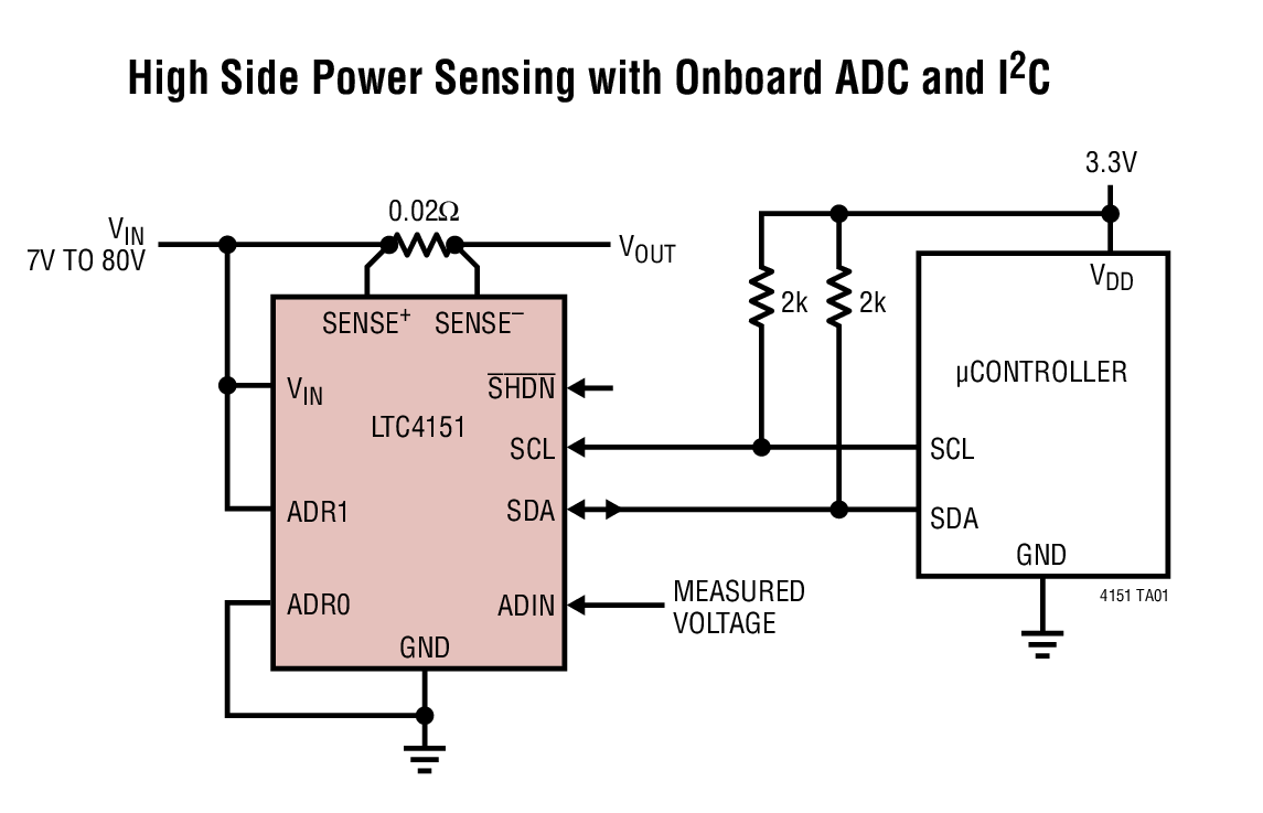
Linear make a range of high-side current monitoring devices.

enter image description here

Figure 1. Linear LTC4151. 0.02 Ω is probably for a high current.

This particular one seems to use serial transmission. Analog versions are available too.

That will give you the current. For power calculation you will need to measure the voltage too - probably from before the voltage regulator so that you measure the losses there too. You then calculate power from \$ P = VI \$. You will have several problems to address including how you average out the current if it varies rapidly.

... feedback input to the Arduino to control some sensors.

Generally you will be reading sensor rather than controlling them.

\$\endgroup\$
0
\$\begingroup\$

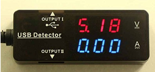
Since your system is cobbled together from ready made subsystem components you may want to consider adding one of these low cost USB power measuring devices inline between your power bank and the rPI and/or the Arduino board. There are several models available from places like eBay and Amazon.

enter image description here

These devices do take some power so you would not want to leave it in place permanently. Use it to profile your system power through the various usage scenarios and then take it back out.

\$\endgroup\$
3
  • \$\begingroup\$ Do you have an idea if the readings of the dongle can be fed to Arduino/rPi? \$\endgroup\$
    – caesar
    Commented Jul 16, 2017 at 5:13
  • \$\begingroup\$ Not with the low cost type of measuring device that I showed here. That is why I suggested that you would use it temporarily to profile your system power usage and then take it out. If you want a real time measuring system that you can auto monitor with the an MCU then you will either have to design and build it or obtain a more expensive measurement device. Such device may be available on a breakout board but would be less likely to have an integrated display. There are medium cost digital multimeters available that run on battery that have a serial interface. (continued) \$\endgroup\$ Commented Jul 16, 2017 at 10:25
  • \$\begingroup\$ (continued from above) At is always possible that a particularly enterprising person could reverse engineer one of these inexpensive USB voltage/current monitors and hack in new software and an extra connection to obtain readout from the device. But that would depend entirely upon the the type of internal MCU used, whether it was designed with access to re-programming pads and if it was even a re-programmable type at all. It would be very unlikely that you could leverage it's existing software. \$\endgroup\$ Commented Jul 16, 2017 at 10:32
0
\$\begingroup\$

Instead of measuring the power consumption interactively, power the whole system from a fully charged battery for couple of hours/days and then measure how much mAh were needed for the batter to be fully charged again. This can give you a good picture of much power was needed over time and also how long can your system run powered on this battery. When changing components you can then compare two measurements if this change was towards power-saving or towards power-consumption.

\$\endgroup\$

Your Answer

By clicking “Post Your Answer”, you agree to our terms of service and acknowledge you have read our privacy policy.

Not the answer you're looking for? Browse other questions tagged or ask your own question.