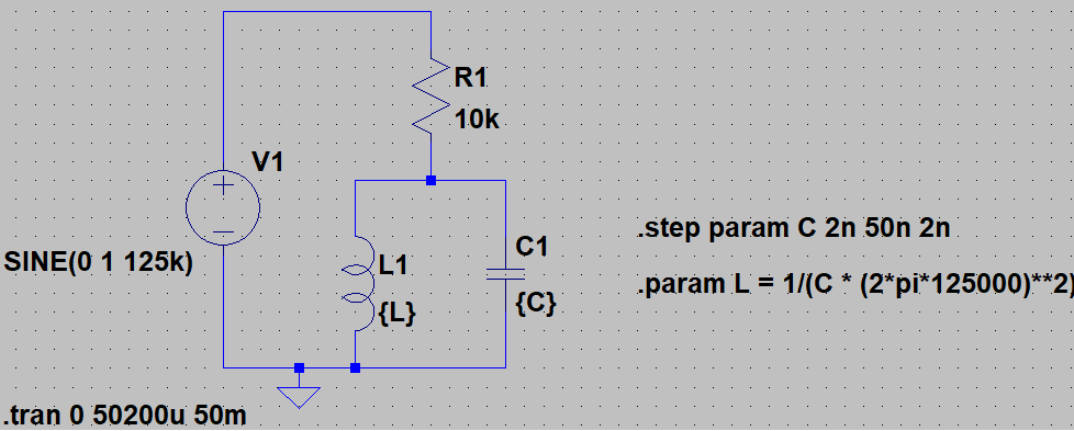
I just simulated the following circuit in ltspice XVII:
A parallel resonant circuit is tuned to 125KHz with varying capacitor sizes. Then a voltage divider is formed with a resistor.
These are my settings for the inductor, capacitor and in the Tool Panel. In my understanding, this should now simulate an ideal inductor without losses and the same for the capacitor.
Using ordinary AC-calculation, the voltage over the resonant circuit should be:
$$ V_{res} = V1 * \frac{\frac{1}{\frac{1}{j \omega L} + j \omega C}}{R + \frac{1}{\frac{1}{j \omega L} + j \omega C}} $$ $$ = V1 * \frac{1}{R*(j \omega C + \frac{1}{j \omega L}) + 1} = V1 * \frac{1}{j R*(\omega C - \frac{1}{\omega L}) + 1} $$ $$ \Rightarrow V_{res} = V1 \quad \forall \quad \omega C = \frac{1}{\omega L} \Rightarrow L = \frac{1}{C \omega^2} $$
So at resonance, when \$ \omega C = 1/(\omega L) \$ the resonant circuit poses an infinite resistance and \$ V_{res} = V1 \$.
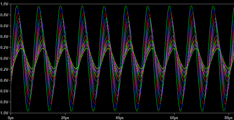
However, LTSpice gives the following simulation results (where smaller C values yield larger amplitudes):
Now I'm wondering how this is calculated by LTSpice. Are there any non idealities that I didn't switch off? Or am I missing something in my calculation?
Any hints would be very appreciated, Thanks in advance.


