3
\$\begingroup\$

I have a device with very strict dimensions; the space electrolytic capacitor will be installed in is exactly 5 mm. I have tried several manufacturers, and learned that some tightly fit, some do not at all. Looking to various datasheets I see dimensioning declared as 5 + 0.5 mm, or 5 ± 0.5 mm. While -0.5 mm would be great, so far I have a bunch of caps which are more than 5 mm.

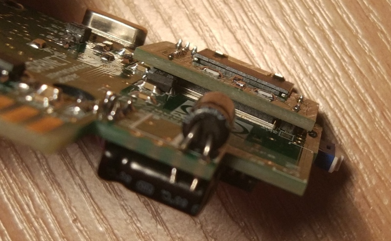
Capacitor is mounted horizontally on the board, thus board at one side, and plastic casing at another (with space of 5 mm).

I am looking to ways how to put these caps in. There're actually two ways -

  1. Increase space where cap would be installed, somehow cutting/using abrasive cloth/heat to melt or anything else on the plastic casing. This plastic casing is transparent, thus working on it will be visible from the outside of the device, and most probably will look ugly;
  2. decrease diameter of the capacitor, and the obvious idea is to remove sleeve off it, it must save several tenths of the millimeter.

Is the second option a good idea from your experience, or I would better work on casing?

Update: thank you for suggestions so far. The capacitor is aluminium electrolytic, here's the set of datasheets: Panasonic, Jamicon and Hitano. Boards are already produced, and must be of 1.6 mm thickness due to edge connector specification.

The peculiarity of the design is that capacitors are mounted this way from the both sides, but only one side does not fit. Caps are 10 uF 25 V bi-polar, not available in 4 mm diameter body.

Here's the pic.

enter image description here

Update: I use bi-polar capacitors. The question is NOT about finding appropriate part, 5 mm diameter caps are already ordered and on their way. Question is about if I can remove black sleeve with marking off the cap on the picture without adverse physical and electrical effect.

\$\endgroup\$
6
  • 2
    \$\begingroup\$ You would remove the infirmation : value etc \$\endgroup\$
    – Solar Mike
    Commented Jul 22, 2017 at 9:26
  • 3
    \$\begingroup\$ If there is space, you could always add a slot into your PCB to give extra room for the capacitor. Alternatively use several lower value capacitors in parallel. Or use a surface mount tantalum capacitor. \$\endgroup\$ Commented Jul 22, 2017 at 9:30
  • \$\begingroup\$ If you can't substitute a ceramic SMT cap, think of specifying a thinner PCB, then a small slot in the PCB. \$\endgroup\$ Commented Jul 22, 2017 at 11:33
  • 1
    \$\begingroup\$ Your newest update doesn't make sense. You already got an answer to the question whether you can remove the sleeve (yes), so accept that and move on. Frankly, I'd just order better-fitting SMD MLCC (you're not giving technical reason not to), as the price of those is bound to be lower than that of the effort of stripping off the sleeves. SMD 0805 10µF 25V caps could be soldered onto the lead holes instead of your bulky electrolytics, and would be cheap, easier to mount than it would be to strip off the sleeve and a lot smaller. And they are readily available everywhere \$\endgroup\$ Commented Jul 22, 2017 at 14:05
  • 2
    \$\begingroup\$ Removing the sleeve causes no problems electrically in cap operation, ratings etc. Shortcircuit of can to xxx is probably greatest risk. \$\endgroup\$
    – Russell McMahon
    Commented Jul 22, 2017 at 14:21

3 Answers 3

10
\$\begingroup\$

Removing the heat shrinking from the cap has no electrical downside but it is labor intensive. I would first consider routing the capacitor body shape out of the PCB, protrude the cap through the annular, and solder the cap from the bottom of the board - gull wing style.

\$\endgroup\$
3
\$\begingroup\$

You need to substitute your electrolytics caps with ceramic. TDK makes through-hole variants like "FG series" to satisfy the board aesthetics. This is not something like input mike amplifier, it is the headphone output stage, so any possible piezo-effects would not matter.

The one 25V 47uF FG26-type has 5mm pitch and only 3.5mm tall.

\$\endgroup\$
2
\$\begingroup\$

Solving by proof by counterexample:

Caps are 10 uF 25 V, not available in 4 mm diameter body.

Not true. Use a 4mm or 4.5mm diameter cap instead, e.g. Panasonic EEA-FC1E100.

Generally, octopart.com is a nice search engine.

\$\endgroup\$
6
  • \$\begingroup\$ I use bi-polar capacitors, look at datasheets in the question. Will be very glad if you will find bi-polars of 4 or 4.5 mm diameter though. Updated question, though it was not about find me needed part. \$\endgroup\$
    – Anonymous
    Commented Jul 22, 2017 at 13:48
  • 2
    \$\begingroup\$ hm, ok, but I consider non-polarized/bipolar electrol. caps pretty much specialty devices. Why not multi-layer ceramics instead? \$\endgroup\$ Commented Jul 22, 2017 at 13:56
  • \$\begingroup\$ It is located in audio op-amp circuit output (line-out / headphones) with unknown DC polarity bias at the other end. To my knowledge ceramics would not have decent performance in this environment, but I am not an expert in it. \$\endgroup\$
    – Anonymous
    Commented Jul 22, 2017 at 13:59
  • \$\begingroup\$ That is indeed an interesting aspect to your application. Yes, ceramic caps suffer severe value reduction on increased bias. My immediate approach would be to severely overdimension the cap (it's probably just an outpu coupling cup, isn't it?) so that even with some DC offset, you still get enough capacity \$\endgroup\$ Commented Jul 22, 2017 at 14:28
  • \$\begingroup\$ So, maybe 25V 22µF Murata X5R ceramic in 0805 case? murata has a website for each cap that has a plot of the derating due to DC offset \$\endgroup\$ Commented Jul 22, 2017 at 14:34

Your Answer

By clicking “Post Your Answer”, you agree to our terms of service and acknowledge you have read our privacy policy.

Not the answer you're looking for? Browse other questions tagged or ask your own question.