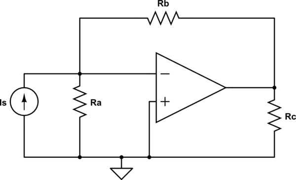
2
\$\begingroup\$

enter image description here

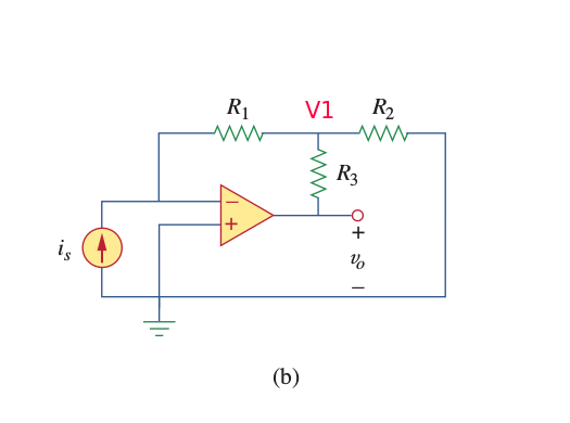
I need to show that for the above current to voltage converter,

\$\frac{V_0}{i_s} = -R_1(1+\frac{R_3}{R_1}+\frac{R_3}{R_2})\$

assuming that the op-amp is ideal,
Voltage at the negative input terminal = \$V_n\$
Current through the negative input terminal = \$i_n\$
Current through the positive input terminal = \$i_p\$
Voltage at the positive input terminal = \$V_p\$
\$V_p\$ = \$V_n = 0V\$
\$i_p = i_n = 0A\$
Using voltage divider rule, \$V_1\$ = \$\frac{R_2}{R_2+R_3}V_0\$
\$i_s = \frac{0-V_1}{R_1}\$, So , using these two equations ,
\$\frac{V_0}{i_s} = -R_1(1+\frac{R3}{R2})\$
Why my answer is wrong ?

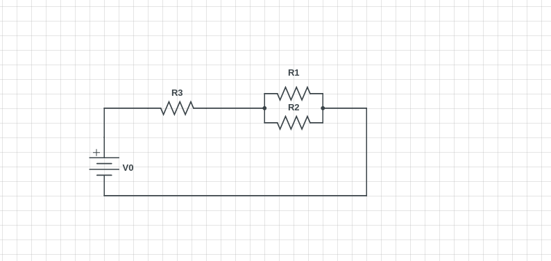
EDIT: I think have figured out the error on my previous calculation . The voltage divider rule still works here like this.
enter image description here

Let, \$R_p\$ be equivalent for R1 and R2
\$R_p = \frac{R_1R_2}{R_1+R_2}\$
\$V_1 = \frac{R_p}{R_p+R_3}V_0\$
\$I_s = \frac{0-V_1}{R_1}\$
\$I_s = \frac{0-\frac{\frac{R_1R_2}{R_1+R_2}}{\frac{R_1R_2}{R_1+R_2}+R_3}V_0}{R_1}\$
After solving this the proof comes.Is there any discrepancy in this?

\$\endgroup\$
4
  • 1
    \$\begingroup\$ There's current through R1, so voltage divider doesn't apply. \$\endgroup\$
    – Chu
    Commented Jul 26, 2017 at 7:15
  • \$\begingroup\$ Use nodal on V1, then substitute your own equation for V1 and solve for the output voltage. \$\endgroup\$
    – jonk
    Commented Jul 26, 2017 at 7:34
  • \$\begingroup\$ Can I assume that \$R_1\$ and \$R_2\$ are parallel as they have same voltage between them? I have edited my question and using that approach I have got the proof . @jonk \$\endgroup\$
    – Utshaw
    Commented Jul 26, 2017 at 7:40
  • \$\begingroup\$ @Utshaw I saw that you placed an answer and then deleted it. Let me show you what I mean. See answer below. \$\endgroup\$
    – jonk
    Commented Jul 26, 2017 at 7:54

2 Answers 2

2
\$\begingroup\$

You already know \$V_1\$. And given your edited/added approach to solving the problem, which works too, I've no problem adding the follow-up to my earlier suggestion that you use nodal analysis.

So just do the nodal for \$V_1\$:

$$\begin{align*} \frac{V_1}{R_2}+\frac{V_1}{R_3}&=i_s+\frac{v_o}{R_3}\\\\ V_1\cdot\left(\frac{1}{R_2}+\frac{1}{R_3}\right)&=i_s+\frac{v_o}{R_3} \end{align*}$$

That's the nodal for \$V_1\$. But you also know that \$V_1=-i_s\cdot R_1\$. (You already said so.) So:

$$\begin{align*} -i_s\cdot R_1\cdot\left(\frac{1}{R_2}+\frac{1}{R_3}\right)&=i_s+\frac{v_o}{R_3}\\\\ -i_s-i_s\cdot R_1\cdot\left(\frac{1}{R_2}+\frac{1}{R_3}\right)&=\frac{v_o}{R_3}\\\\ -i_s\cdot\left[1+ R_1\cdot\left(\frac{1}{R_2}+\frac{1}{R_3}\right)\right]&=\frac{v_o}{R_3}\\\\ v_o&=-i_s\cdot R_3\cdot\left[1+ R_1\cdot\left(\frac{1}{R_2}+\frac{1}{R_3}\right)\right]\\\\ \frac{v_o}{i_s}&=- R_3\cdot\left[1+ R_1\cdot\left(\frac{1}{R_2}+\frac{1}{R_3}\right)\right]\\\\ \frac{v_o}{i_s}&=- \left(R_3+ \frac{R_1 R_3}{R_2}+R_1\right)\\\\ \frac{v_o}{i_s}&=- R_1\cdot\left(1+\frac{R_3}{R_1}+ \frac{R_3}{R_2}\right) \end{align*}$$

Which amounts to what you said you needed to prove.

However, it wouldn't hurt to go one more step:

$$\begin{align*} \frac{v_o}{i_s}&=- R_1\cdot R_3\left(\frac{1}{R_1}+ \frac{1}{R_2}+\frac{1}{R_3}\right)\\\\ &=-\frac{R_1\cdot R_3}{R_1\:\mid\mid\: R_2\:\mid\mid\: R_3} \end{align*}$$

Since all three resistors are attached to voltage sources, and a common node, you'd expect that they are in some way parallel to each other. The above equation makes that fact explicit.

\$\endgroup\$
2
  • \$\begingroup\$ Thanks ,I have understood it.But have you seen my **Edited ** section of question ?Can I consider that R2 and R1 are in parallel ?As this question has come across my mind after solving that way I deleted the answer and posted it in a separate section inside the question . @jonk \$\endgroup\$
    – Utshaw
    Commented Jul 26, 2017 at 8:12
  • \$\begingroup\$ @Utshaw Yes, that would work as well. \$\endgroup\$
    – jonk
    Commented Jul 26, 2017 at 8:19
0
\$\begingroup\$

To solve the circuit you may try to apply delta-wye (triangle-star)transformations, if you know them. The three resistors are in a star (aka wye) configuration.

If you substitute them with the equivalent triangle (aka delta) configuration, you get a circuit like this:

schematic

simulate this circuit – Schematic created using CircuitLab

Then you can convert the input current source with Ra in parallel to a voltage source and you get the classic inverting amplifier circuit.

\$\endgroup\$
1
  • \$\begingroup\$ But as \$V_n\$ is 0V, I think , voltage divider still works here . \$\endgroup\$
    – Utshaw
    Commented Jul 26, 2017 at 7:31

Your Answer

By clicking “Post Your Answer”, you agree to our terms of service and acknowledge you have read our privacy policy.

Not the answer you're looking for? Browse other questions tagged or ask your own question.