It seems to me that the maximum current output of a linear regulator should be determined primarily by power / heat dissipation, not the actual current. For instance, a 3.3V regulator that has an output current of 100mA with a 40V input could not easily dissipate the voltage drop (3.67 W), whereas it would have no problem providing 1A if it only had to drop the input voltage by .5V (0.5 W). I'm guessing the input and output capacitors would have to be changed to keep the regulator stable, but is there any other reason for these listed current output limits other than a general guideline?
4 Answers
Good question.
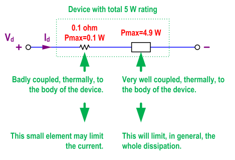
Almost always, what damages things is heat, not current. The answer to your question is in the difference between local and global, or between sub-parts and the whole thing. The current may go through several sub-parts, and each one of them may have different power ratings. A bonding wire may have, by itself, a dissipation limit that is way below that of the whole device. A series sub-part, that needs to be there for whatever reason, may have a dissipation limit lower than that of the main sub-part. For instance, because it has a small volume, and a small surface in contact with the rest of the device, and cannot put out heat at the same rate as the main sub-part. In cases like these ones, it makes sense to specify a limit for the current, even after having specified a limit for the total dissipation, because those little, "secondary" sub-parts may not be able to dissipate heat at the same rate as the device as a whole.
Just an example. Imagine the situation in the following figure. The power rating for the whole device is 5 W. It would look like operating the device at \$V_d\$=2 V and \$I_d\$=1.5 A would be within safe limits, because \$P_d=V_d·I_d=2·1.5=3\$ W < 5 W. The global heat dissipation would be below its corresponding limit. However, \$I_d^2·0.1=1.5^2·0.1=0.225\$ W > 0.1 W, so that small sub-part would be exceeding its local dissipation limit, and hence the need to specify \$I_{dmax}\$ in addition to \$P_{max}\$. But the key is that, even for that current limit, the real reason behind it is heat, not current by itself. Except for a few cases (like electromigration), current by itself does not directly damage anything.

General guidelines? They're actual limitations, most of the times deliberately designed for. This is often with maximum power dissipation in mind. That dissipation situation can be different for different implementations. It's up to the design engineer to ensure that the device is used within its specifications. It would be silly to say the 3.3V regulator should not exceed 10mA at 40V input if the designer has a good solution to get rid of the heat at 100mA.
That's why thermal resistance is specified in the datasheet. Thermal resistance from junction to case, and from case to ambient. The designer may use a heatsink which has its own thermal resistance, or mount the device on a large copper plane of the PCB. The datasheet gives you the information to allow you to use a device to the max.
-
\$\begingroup\$ I understand that, but my question is more along the lines of whether I can EXCEED 100mA by a large amount without risk if I ensure that I can dissipate the required heat, or if there is some other reason besides heat that makes the limit 100mA. \$\endgroup\$ Commented May 17, 2012 at 13:54
-
\$\begingroup\$ @QuestionMan - Is that the same regulator that you also used for the 1A? Then the 100mA is not a limit, if you can ensure that the junction temperature stays below the maximum value given in the datasheet. It's up to your design skills to stay within these limits. In PCs where a small CPU can dissipate as much as 100W they finally came up with water cooling. \$\endgroup\$– stevenvhCommented May 17, 2012 at 14:02
-
\$\begingroup\$ Well, I'm not actually using it for 1A (I wouldn't attempt to make something that I actually needed to work that exceeded datasheet limits), but was just wondering how those numbers were determined. \$\endgroup\$ Commented May 17, 2012 at 14:38
-
\$\begingroup\$ The problem is that if you exceed the maximum current, you may only be generating a small amount of heat, but in a specific little component inside that little IC. Something can burn out inside the chip without causing a large case temperature. The limitations of the device should be observed in all dimensions. If you can pump more current with adequate cooling, that would be something that should be published as a derating. E.g. so much current allowed at such an such temperature, and then so many miliamps "off" for every one degree rise. \$\endgroup\$– KazCommented May 17, 2012 at 21:37
No, heat is not the only thing limiting linear regulators. Regardless of heat, a particular regulator can only handle some maximum current. That is because the parts used to implement that regulator can only handle that current.
Look at the spec for any transistor, and you will see a maximum current and maximum power limit. Both are real. Linear regulators are made from transistors and other devices with maximum current capability, so have a maximum current capability themselves.
Consider a unrealistic example that nonetheless illustrates this point. Suppose you had a linear regulator chip that was well cooled and capable of high current itself, but the bond wires between it and the pins of course have a finite thickness and current carrying capability. Those bond wires will fuse at some current, regardless of how much power the chip is dissipating. The bond wires don't see the voltage drop of the regulator, only the current thru them.
You asked
is there any other reason for these listed current output limits other than a general guideline?
'Absolute survival' and 'recommended operating' limits are set by the manufacturer and you exceed them at your peril. Even "recommended operating limits" are not general guidelines - they are lines in the silicon that you do not cross in a proper design.
No "properly designed solution will exceed either of these except when the designer has the resources and capability to qualify the components themselves - and even then they are at the mercy of the manufacturer changing the parameters in such a way that it still meets spec sheet specs but no longer meets the designers special case specs.
A 100 mA regulator compared to a 1A one may have less silicon overall, have a lower capability output transistor, not be able to or not be designed to drive the output stage hard enough to keep it in saturation (bipolar) or fully enhanced mode (MOSFET).
For below:
Rth = thermal resistance in degrees C or K rise per watt dissipated.
Rth_jc = thermal resistance junction to case
= degrees rise of junction above case temperature per Watt of dissipation.Rth_Ja = thermal resistance junction to air (no heat sink)
Rth-ca = thermal resistance from case to air = heatsink and any mounting hardware.
You say
For instance, a 3.3V regulator that has an output current of 100mA with a 40V input could not easily dissipate the voltage drop (3.67 W), whereas it would have no problem providing 1A if it only had to drop the input voltage by .5V (0.5 W).
but the former is not necessarily true - thermal limits are often not the main factor, although the example you suggested is a stiff one.
eg if you accepted a 130 C junction temperature and designed to a 40C heatsink temperature then the part would need an internal thermal resistance Rth_jc of <= Tdrop/ Watts_dissipated
= (130-40)C /3.67W = 90/3.67 ~= 25 C/W
This is about half the rating of a TO92 part at around 50 C/W
The nice people at Infineon provide this TLE4266-2 regulator in SOT223-4 case with 18 k/W Rth-jc and an allowable 150 C max die temperature. It's rated at 150 mA max. The soldered tab on the package and the similar SOT89 pkg mean that a Rth-jsink of something like the above figure could be obtained.
SOT89 packages are usually specified only for Rth-ja despite the tab - wityh figures of arounf 50 k/W being given. A Rth-jc of far less than half that would be expected as Rth-ca is not going to be low due to being mainly plastsic exposed to air.
Finally, the nice folks at Zetex / Duiodes Inc can always be relied on to do better than almost any and offer AP78L05 regulator with 18 C/W in SO8 on 2 Oz copper, FR4 and 25 C/W for SOT89 with quie modest "minimum recommended pad layout.
SOT89 copper for 25 C/W


