1
\$\begingroup\$

I have a basic conecptual question related to series RLC circuit response Assuming that I have sinusoidal source of the form $$ V_{source}=V_m*sin(\omega*t) $$ The equation for voltages in RLC circuit can be given as $$ \ d''i(t)/dt + R/L*di(t)/dt + i(t)/(L*C) = V_{source} $$ I hope the above equation is correct. Now the solution to this equation is $$ i(t) = I(t)_{ss} + I(t)_{tr} $$ where \$I(t)_{ss}\$ is the steady state response (otherwise known as solution to non homogenous equation/forced response/particular solution) and \$I(t)_{tr}\$ is transient response (otherwise known as general solution/solution to homogenous equation/natural response).

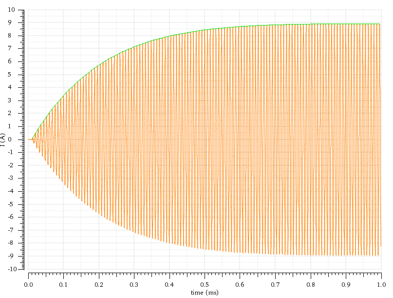
Lets assume that frequency of \$ V_{source} \$ is equal to resonance frequency of the RLC circuit. Now \$I(t)_{tr}\$ will tell you whether the circuit is under/over/critically damped and \$I(t)_{ss}\$ will give you the maximum amplitude of current which in this case will be \$ V_m*cos(\omega*t)/R \$ since the circuit is in resonance. But i get the following responseCurrent in RLC circuit with a sinusoidal forcing function at resonance Now in the steady state (roughly after 0.8 ms), the current is completly defined by \$I(t)_{ss}\$.
So my questions are:

  1. What is the governing equation for the rise of current in RLC series circuit (basically I need the governing equation for the green curve). I tried to simulate the complete equation in Matlab i.e steady state + transient thinking that the transient solution should take care of the initial green curve but apparently that is not the case

  2. If the steady state solution describes the current after 0.8 ms then transient solution should be able to describe the green curve. The total solution should effectively describe the current profile shown in the picture. Is this correct?

  3. To solve the homogenous equation, the initial condition is \$ i(0) = 0\$ and final condition should be \$ i(\inf) = V_m * sin(\omega*t)/R\$. Am I correct? How to include these conditions to find constants in homogenous solution?

  4. This kind of current behavior is not covered in most of the literatures on the internet. Why not?

  5. In order to define the green curve i will need an equation in the form \$ i(t) = {V_m(t)*sin(\omega*t)}/R\$. Am i correct?

Any help will be greatly appreciated. I know there are tonnes of forums/literature discussing the RLC circuit, but none has given me answers to my questions. I still remain confused.

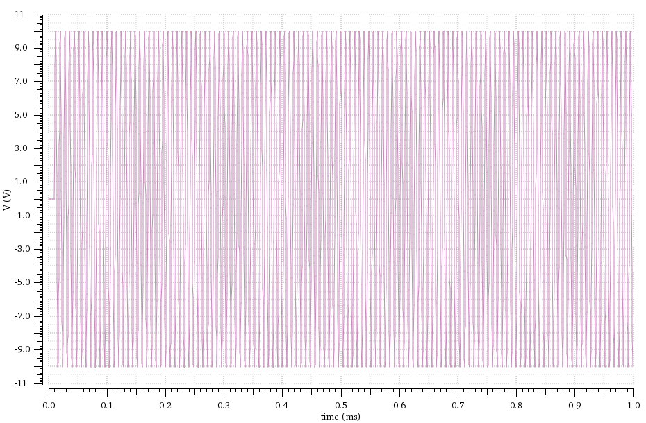
edit: I have added the input signal Input source signal

\$\endgroup\$
7
  • \$\begingroup\$ First you say your source has \$V(t) = V_m\sin(\omega t)\$ but then you simulate with \$V(t)=V_m\sin(\omega t)u(t)\$ and ask a bunch of questions about the transient response. Which situation are you actually interested in? \$\endgroup\$
    – The Photon
    Commented Aug 4, 2017 at 14:55
  • \$\begingroup\$ Nope I have the source signal as V(t)=Vmsin(ωt) in the simulations. Otherwise also isnt V(t)=Vmsin(ωt)u(t) = Vmsin(ωt) for t>0? How does multiplying unit step change anything? I am only interested in the equation describing amplitude of current (or rise in current) with respect to time, the green curve as mentioned before. I have added the input signal waveform in the post \$\endgroup\$
    – RAN
    Commented Aug 4, 2017 at 16:25
  • \$\begingroup\$ The way the simulator works, it assumes no signal before t=0, so it's equivalent to \$V_m\sin(\omega t)u(t)\$. Otherwise you wouldn't see the transient behavior for the first milliseconds of the simulation. (Notice when you plot the input signal, you don't show any signal before t=0, and the simulator wouldn't even let you produce a plot of the signal before t=0). \$\endgroup\$
    – The Photon
    Commented Aug 4, 2017 at 17:03
  • \$\begingroup\$ Yes I agree from simulator point of view, but for the scope of the problem i asked, how does V(t)=Vmsin(ωt) and V(t)=Vmsin(ωt)u(t) (= Vmsin(ωt) for t>=0) make any difference. You considered them as two different situations, while i consider them to be the same. \$\endgroup\$
    – RAN
    Commented Aug 6, 2017 at 17:28
  • \$\begingroup\$ If the sine wave had been input continuously, you wouldn't see the transient behavior that you're asking about. \$\endgroup\$
    – The Photon
    Commented Aug 6, 2017 at 18:14

2 Answers 2

1
\$\begingroup\$

It's, arguably, easier to solve this in Laplace and, if the system were 1st order, the solution will be of the form: \$\small A(1-e^{-at})sin (\omega t+\phi)\$. You have an overdamped 2nd order system, so the final equation will have two transient exponentials.

A differential equation solution will obviously give the same answer, but will require integration by parts, probably a couple of times. But it's a nice exercise.

The following analysis has been added to the original answer

The differential equation relating current, \$\small I(t)\$, and applied voltage, \$\small v=V_msin(\omega t)\$, in a series RLC, circuit is:

$$\small \ddot I+\frac{R}{L}\:\dot I+\frac{1}{LC}\:I=\frac{1}{L}\:\dot v $$

evaluating \$\small \dot v\$, and writing the 2nd order term in standard form:

$$\small \ddot I+2\zeta\omega\:\dot I+\omega^2\:I=\frac{V_m}{L}\:\omega\:cos(\omega t) \:\:\:...\:(1)$$

where, in this case, the applied sinusoidal voltage is at the natural frequency, \$\small \omega=\frac{1}{\sqrt{LC}}\$

The particular integral (steady state solution), given a sinusoidal input, is:

$$\small I_{ss}= A\:sin(\omega t)+B\:cos(\omega t)$$

Differentiating \$\small I_{ss}\$ twice:

$$\small \dot I_{ss} =A\:\omega\:cos(\omega t)-B\:\omega\: sin(\omega t)$$ $$\small \ddot I_{ss} =-A\:\omega^2\:sin(\omega t)-B\:\omega^2\: cos(\omega t)$$

Substituting for \$\small I\$, \$\small \dot I\$, and \$\small \ddot I\$ in \$\small (1)\$:

$$\small -2\zeta\omega^2B\:sin(\omega t)+2\zeta\omega^2A\:cos(\omega t)=\frac{V_m}{L}\:\omega\:cos(\omega t) $$

Hence, comparing coefficients, $$\small B=0$$

$$\small A=\frac{V_m}{2\zeta\omega L}=\frac{V_m}{R}$$

and $$ \small I_{ss}=\frac{V_m}{R}sin(\omega t)$$

The homogeneous solution (transient solution) is of the form:

$$\small I_{h}= e^{-\alpha t}\left ( D\:sin(\omega t)+E\:cos(\omega t)\right )$$

and the overall expression for \$\small I\$ is, thus:

$$\small I=I_h + I_{ss}= e^{-\alpha t}\left ( D\:sin(\omega t)+E\:cos(\omega t)\right )+\frac{V_m}{R}sin(\omega t)$$

By inspection, initial conditions are: \$\small t=0;\: I=0;\:\dot I=0\$

The first condition gives: \$\small E=0\$, and the second condition, obtained by evaluating \$\small \dot I\$, gives: $$\small D=-\frac{V_m}{R}$$

Therefore the final expression for \$\small I\$ is:

$$\small I=\frac{V_m}{R} \left (1-e^{-\alpha t}\right )\:sin(\omega t)$$

\$\endgroup\$
5
  • \$\begingroup\$ thank you for your response, since it is an RLC circuit the system is of second order. Can you please point me to any literature if you have any? \$\endgroup\$
    – RAN
    Commented Aug 4, 2017 at 12:13
  • \$\begingroup\$ I've corrected the 1st order assumption. Are you going on the differential equation route? \$\endgroup\$
    – Chu
    Commented Aug 4, 2017 at 12:16
  • \$\begingroup\$ Actually the current response you see is of an under-damped system. (L=108 uH, C= 15 nF, R = 1 ohm). So far i have revisited all the equations in differential, so yes I would like to continue differential way. I will also verify the same using Laplace. Will be a good exercise like you mentioned before \$\endgroup\$
    – RAN
    Commented Aug 4, 2017 at 12:25
  • \$\begingroup\$ See addition to original answer. \$\endgroup\$
    – Chu
    Commented Aug 4, 2017 at 23:33
  • \$\begingroup\$ Thank you Chu for the detailed evaluation. I know where I went wrong, it was while finding the constants. Need to really brush up my basics! \$\endgroup\$
    – RAN
    Commented Aug 6, 2017 at 17:20
0
\$\begingroup\$

Have a look here, you might be able to change the values and get an answer for your particular problem.

Also, your final condition should be changed, you cannot define sin(t) at t=inf. Instead, maybe put an initial condition di/dt=0 at t=0

\$\endgroup\$
4
  • \$\begingroup\$ Hi, for real and not equal roots, you will need two equations to find two constants. One of the equations is initial condition and the other one as final condition. So what should be the final condition in this case? \$\endgroup\$
    – RAN
    Commented Aug 4, 2017 at 13:37
  • \$\begingroup\$ Hi, my bad, i need \$ i(0) \$ and \$ i'(0) \$. Now the current in the beginning is \$ i(0) = 0 \$, what should be \$ i'(0) \$ ? Is it the slew rate of the current the moment a sinusoidal voltage source is applied? \$\endgroup\$
    – RAN
    Commented Aug 4, 2017 at 16:30
  • \$\begingroup\$ If I remember correctly, I guess that since your circuit is at rest for t<0, you also have that i'(0)=0. Try to solve the equation for that case and see if you get the same curve \$\endgroup\$
    – A.Riga
    Commented Aug 5, 2017 at 13:31
  • \$\begingroup\$ Hi, thank you for sharing the document, it was useful to look at the problem from different angle. \$\endgroup\$
    – RAN
    Commented Aug 6, 2017 at 17:30

Your Answer

By clicking “Post Your Answer”, you agree to our terms of service and acknowledge you have read our privacy policy.

Not the answer you're looking for? Browse other questions tagged or ask your own question.