1
\$\begingroup\$

Phototransistors are a new tool for me, and I'm wondering how to select one that will match a specified source (LED worklight, color temp 5000K, wavelength unspecified). My prototype works but apparently does not match the light source. Of course the data sheet for the transistor (ROHM RPM075PTT86) specifies its spectral response. I can't find out how to correlate a color temp of 5000K to a wavelength. There must be a better way than trial and error. For reference the app is a conveyor package detector, light is overhead strip about 2' above the surface, sensors are in a strip across the conveyor. Any suggestions appreciated! Harry

Datasheet HERE

\$\endgroup\$
9
  • 1
    \$\begingroup\$ See: digikey.co.uk/en/articles/techzone/2013/apr/… \$\endgroup\$
    – jonk
    Commented Aug 7, 2017 at 15:23
  • \$\begingroup\$ Each situation is its own case. It sounds as though you've been embroiled in the idea of re-inventing wheels. I'm pretty sure lots of people have already solved the conveyor belt package detection problem and probably done a yeoman's job of it. What's your situation that requires you to do something new to your understanding? \$\endgroup\$
    – jonk
    Commented Aug 7, 2017 at 15:36
  • \$\begingroup\$ @jonk the second two graphs on there is the answer, you should use those. \$\endgroup\$
    – Passerby
    Commented Aug 7, 2017 at 16:15
  • 1
    \$\begingroup\$ An LED characterized by a color temperature is designed to illuminate things to be viewed by human eyes; it is not optimized for detection by another semiconductor device. Your detector has good response over the visible band, so I would expect this to work reasonably well. Improvement will indeed be a matter of trial and error (or getting access to a spectrometer to measure your LEDs spectrum). \$\endgroup\$
    – The Photon
    Commented Aug 7, 2017 at 16:24
  • \$\begingroup\$ @Passerby Hmmm? \$\endgroup\$
    – jonk
    Commented Aug 7, 2017 at 16:36

4 Answers 4

2
\$\begingroup\$

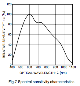
Your photo transistor is optimally responding to 600 nm. enter image description here

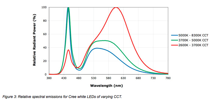
White leds of 5000k tend to have their heighest peak in the blue range of 450 nm and a lower hump over 525 to 550 nm. enter image description here

The setup is not ideal, but should still have some reasonable response, as long as you properly aim them at the light source. Both the transistor and the light source spectrum peaks are curves, and should work even if not directly matched, as long as the output is in the curve. Without knowing your specific lights spectral range, we cannot give you better guidance.

\$\endgroup\$
0
\$\begingroup\$

5000K corresponds to green/yellow (if it is black body radiation). So your phototransistor should have a response curve in the visible part of the spectrum, between (approx) 700nm to 400nm

\$\endgroup\$
5
  • \$\begingroup\$ LEDs are decidedly not black body radiators. Google "white led spectral distribution" to see some examples. \$\endgroup\$
    – jonk
    Commented Aug 7, 2017 at 15:22
  • \$\begingroup\$ @jonk Yes, but they are in the visible range which is between 700nm and 400nm, so it doesn't matter \$\endgroup\$ Commented Aug 7, 2017 at 15:46
  • \$\begingroup\$ That is my first reaction. But then my second one is that it all depends and I cannot say. The OP says they have it working after a degree but are still asking for help. Which tells me there is some problem yet. And so I'm far less sure of myself. In any case, I was addressing myself to the "black body radiation" tidbit and clarifying that point. \$\endgroup\$
    – jonk
    Commented Aug 7, 2017 at 15:52
  • 1
    \$\begingroup\$ @jonk Well, the problem is that they should really be using modulated IR light with a filter on the receiver (both optical and electronic). Or more simply, buy a COTS module designed for such \$\endgroup\$ Commented Aug 7, 2017 at 19:07
  • 2
    \$\begingroup\$ I agree with your comment about modulation and optical filtering/baffles, etc. Get rid of as much of the problem as you can before it reaches the circuit. And then to deal with what you are forced to accept, modulate and extremely narrow-band filter the result. As in "21.31 Hz." Like, that narrow. \$\endgroup\$
    – jonk
    Commented Aug 7, 2017 at 19:19
0
\$\begingroup\$

This answer addresses part of your question only.
enter image description here

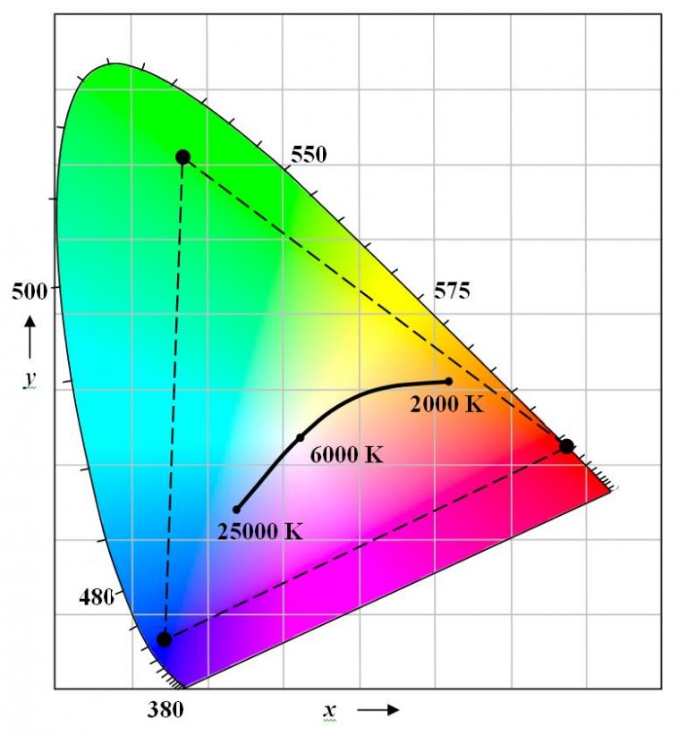
*Figure 1. Typical RGB LED module color gamut and white colour temperatures. Source: AGI.

The human eye has three sets of rods sensitive to short, medium and long wavelengths which roughly correspond to blue, green and red respectively. The brain converts the relative stimulus strength received by each rod to a 'colour'. With an RGB source with wavelengths identified by the black dots on the chart of Figure 1 you can simulate any colour inside the triangle. Note that you are not generating that wavelength - just fooling the eye with the relative strengths of each component.

Some white LEDs use a blue light with yellow phosphors. By controlling (in the design and manufacture) the mix of blue and yellow the colour temperature can be controlled roughly along a straigh line - an extended line from 25000 K through 6000 K over towards yellow.

Note that in both cases described above that the light sources will not be truly monochromatic but will have a spectral spread.

I can't find out how to correlate a color temp of 5000K to a wavelength. There must be a better way than trial and error.

If you have enough time and interest you could make a spectrometer for your phone. See PublicLab smartphone-spectrometer.

For reference the app is a conveyor package detector, light is overhead strip about 2' above the surface, sensors are in a strip across the conveyor.

You haven't linked a datasheet for your sensors but it's much more likely that ambient light is swamping the measurements. Edit your question to show your circuit - there's a simple schematic button on the editor toolbar - and readings obtained with target present and absent.

\$\endgroup\$
0
\$\begingroup\$

Thanks to all for the good info. My original question betrays my ignorance of photo-electronics. In retrospect, I have found that the source @5000K resembles white light ("early sunlight", per mfr), and as such would hardly have a discrete wavelength. One of the comments is quite correct in that the 600um detector is well matched to the light from the source. I should have realized this because the source is used to light the existing detector strip (which I am replacing, and which is a very specific design) without any problems. I'm embarrassed to say that the issue is more related to the bias of the photo-transistor. I believe it is true that the higher the value of the pullup resistor the more 'sensitive' it is. I found this to be true when I changed from 4.7K to 21K pullups. (not sure how to import drawings, but in this circuit the emitters of the detectors are grounded, pullup resistor to 5V, also to the gate of a mosfet, the open drains of which are wire ored to the processor pin). This increased the sensitivity dramatically. Should have been obvious- if the pt is a current modulator, then the IR drop will be greater for a greater resistor value, within reason.

\$\endgroup\$

Your Answer

By clicking “Post Your Answer”, you agree to our terms of service and acknowledge you have read our privacy policy.

Not the answer you're looking for? Browse other questions tagged or ask your own question.