0
\$\begingroup\$

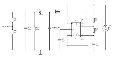
I have built a grain moisture sensor using a 555 timer and an arduino, as shown in the figure:

Circuit .

The sensor is composed of a two parallel aluminum plates (as in a capacitor):
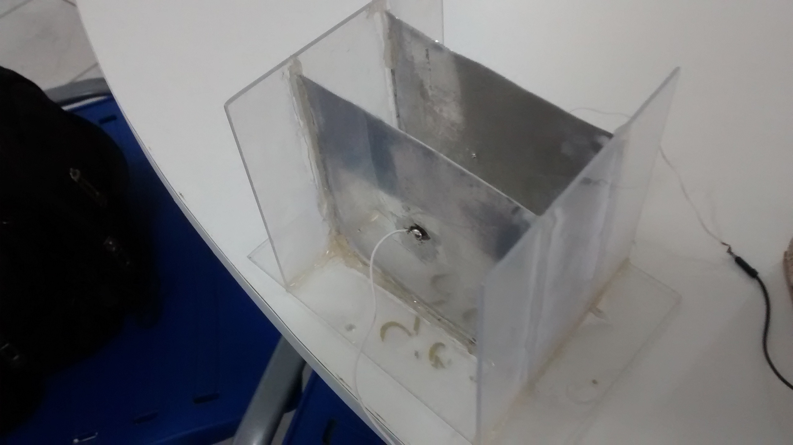
enter image description here The output of this circuit is connected to analog arduino pin A0. I have noticed that the higher the moisture of the grain, the lower is the voltage read by the analog pin. From basic phyisics:

\$ C =(ε_0 ε_R A)/d\$ - in which \$ ε_R\$ is the dielectric of the capacitor, so the higher the moisture the higher the capacitance of the sensor is.

I am having trouble understanding why voltage drops when moisture is higher. Why does the voltage drop when the moisture is higher?

\$\endgroup\$
0

2 Answers 2

2
\$\begingroup\$

From basic capacitor physics, we know that capacitance, charge, and voltage are related by

$$V = \frac{Q}{C}$$

and given that parallel plate capicatance is described by $$C = \frac{\epsilon A}{d},$$

If the total charge stays constant, then the voltage across the capacitor will decrease with increasing permittivity.

$$ V \varpropto \frac{\alpha}{\epsilon}$$

(\$ \alpha \$ represents the constants of charge, area, and distance.)

\$\endgroup\$
1
  • \$\begingroup\$ \$ .. \$ for inline MathJAX on EE.SE. \$\endgroup\$
    – Transistor
    Commented Aug 10, 2017 at 19:22
0
\$\begingroup\$

As you said, the higher the moisture, the larger the capacitance C of your sensor.

The larger the capacitance C, the lower the cut-off frequency of the low pass filter (formed by R3-Sensor). The lower the cut-off frequency, the smaller the peak voltage before D1 will be, because you're removing more and more high frequency components. Eventually, if C could go to a very big value, you'll end up with just the DC component of the generated square wave. That DC component is determined by the product of the duty cycle of the square wave, which is R2/(R1+R2) and the value of V1.

Beside, instead of using this arrangement, where you check the analog voltage produced by this circuit, you could use the sensor itself instead of C1 (change the resistor values R1 and R2 accordingly), and measure the frequency (with a capture pin on your arduino) of Pin 3 of U1. You'll save R3, D1, C3, R5, R6. In this case, the larger the moisture, the lower the frequency.

\$\endgroup\$

Not the answer you're looking for? Browse other questions tagged or ask your own question.