0
\$\begingroup\$

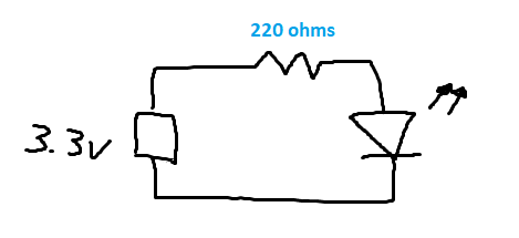
Given the following circuit, it seems like we could use ohms law to conclude that current = voltage / resistance. With a source voltage of 3.3 and a resistance value of 220, current = 3.3 / 220 = .015 amps, however, after measuring the current with a multimeter, this value was wrong.

The actual measured current was .0061 amps.

enter image description here

So it seems that we need to subtract another value from the source voltage to get the right current result, I believe this value is the voltage drop.

What value do we subtract from the source voltage? Do we select the voltage drop of the resistor or the voltage drop of the LED and why?

It seems that based on the obvious values of a source voltage and a resistor, we need to include less obvious values in the calculation of current which seem to be only available by circuit measurements or by consulting a spec sheet of some sort.

\$\endgroup\$
1
  • \$\begingroup\$ After doing some research, I have reached the conclusion that when determining current, the value we use for voltage is equal to the voltage drop introduced by the resistor. I guess one could say that when using a resistor in series, the "true source voltage" value to be used in ohms law calculations is not the battery's voltage but the voltage drop introduced by the resistor. \$\endgroup\$
    – user158409
    Commented Aug 13, 2017 at 3:04

2 Answers 2

2
\$\begingroup\$

Let's look at Ohms Law \$ V = IR \$

What this means is that the voltage between two points, is the current that is between those 2 points, and the resistance between those 2 points.

In your analysis you did the following: $$ I = \frac{V}{R} = \frac{3.3}{220} = 15mA $$

Since voltage is a potential difference, the 3.3V is with respect to ground. So the two points we are looking at, is the supply rail (3.3V) and ground (0V). The resistance between these two points as initially placed, is 220 ohms. That means that the LED has NO resistance at all. And this is where it broke down. You made an assumption that the LED had no resistance, and it does (it's a weird type of resistance called dynamic resistance - but don't worry about that one right now).

But when an LED has current passing through it, it has with it a forward voltage drop that will approximately be constant. Depending on the color of the LED, it will have different forward voltage drop. Red led's are about ~2V.

So if we try again with this new knowledge, we can come up with the following:

$$ I = \frac{V}{R} $$ $$ I = \frac{\Delta V}{R} $$ $$ I = \frac{3.3V - 2V}{220} $$ $$ I = \frac{1.3V}{220} = 5.9mA $$

\$\endgroup\$
0
\$\begingroup\$

The LED has a forward voltage across it, which is relatively constant with current. This voltage will vary depending on the color of the LED, as the wavelength of the light is directly related to the band gap energy and therefore the forward voltage.

In your case, this forward voltage is 3.3 V - 220 Ω * 6.1 mA = 1.96 V, which sounds exactly right for a red LED.

When calculating current through a series circuit of an LED and a resistor, there are several different methods depending on how accurate you want to be: typically, a constant-voltage approximation is sufficient (as shown above). For more refined calculations, an iterative method using various diode voltage models can be used.

I would recommending reading Wikipedia: LED circuit and Sparkfun: LEDs.

To round things out: typically, the above calculation is done the other way around. That is, let's say you have an LED with a forward voltage of 2.5V (from the datasheet), recommended operating current of 10 mA, and you want to operate it from 5.0V: (5.0V - 2.5V)/10mA = 250 Ω. So you would select whatever resistor is nearest to 250Ω that is readily available.

\$\endgroup\$

Your Answer

By clicking “Post Your Answer”, you agree to our terms of service and acknowledge you have read our privacy policy.