9
\$\begingroup\$

How can a signal (e.g. an analog radio signal) be 'stretched' in time, so that the frequency is halved and the signal takes twice as much time? It's straightforward to do in a computer, but can it be done with analog components?

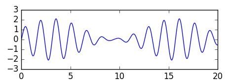
The transform I'm looking for is the same as recording an audio tape and then playing it at half the speed, so translating an input signal of for example example input signal
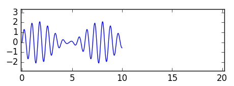
to

example output signal

(This is different from what a heterodyne radio receiver does: it shifts a signal from a high to a lower frequency, but the signal still takes up the same amount of time.)

Recording and reading back at a slower speed would be one way to do this, but that would require slow mechanical components and not be able to deal with faster signals.

Background: I'm not building anything for which I need this, but I'm wondering if something like time division multiplexing could work in the pre-digital age or what it would take to create it. That is also why a method like recording to tape and slowed down playback would not work. If the multiplexed pieces of signal are short, the mechanical systems of a tape would not be able to keep up.

Edit The relation with time division multiplexing: I was thinking that tdm could be implemented with such a technique. Take two continuous signals, split them up into (say) microsecond intervals, squeeze each microsecond into half a microsecond (increasing the frequency), then interleave the squeezed segments of signal from both streams. To demodulate, reverse the process by stretching the odd or even intervals.

\$\endgroup\$
18
  • 7
    \$\begingroup\$ 1. How will your design decide (in the real world) what time is "t=0"? 2. Regardless of what kind of technology is used, producing the output at (for example) t=100 requires remembering what the input was at t=50. So some kind of memory is required. And memory is never unlimited. So how long do you need this to work for before it runs out of memory? \$\endgroup\$
    – The Photon
    Commented Aug 28, 2017 at 16:18
  • 1
    \$\begingroup\$ Also, I'm not clear how this question relates to time division multiplexing; can you say more about why you think there's a connection? \$\endgroup\$
    – The Photon
    Commented Aug 28, 2017 at 16:21
  • 25
    \$\begingroup\$ Play it back from a vehicle moving away from you at Mach 0.5. \$\endgroup\$
    – user16324
    Commented Aug 28, 2017 at 16:25
  • 1
    \$\begingroup\$ The audio bandwidth of traditional telephone service is ~3.3 kHz, with corresponding Nyquist sample rate 6.6 kSps. If you did TDM with us-scale divisions, so long as you gave each channel a slot at least every 150 us, the signal could be reproduced directly by low-pass filtering without any need for this time-stretching idea. \$\endgroup\$
    – The Photon
    Commented Aug 28, 2017 at 16:53
  • 2
    \$\begingroup\$ There was a radio system in Germany that really used a bucket brigade to open up short "time slots" in an analog system. It used multiple receivers and syncronized transmitters to build a very large radio network that operated on a single transmit/receive frequency pair. The time slots were used to transmit operating data (signal strength and other info) in band with the audio. If it worked right, you had enormous coverage without changing channels. If it didn't work right, you still had the coverage, but it sounded like you were trying out shout a table saw. \$\endgroup\$
    – JRE
    Commented Aug 28, 2017 at 19:28

8 Answers 8

16
\$\begingroup\$

There IS one analog technology that can be used to do the job ... the CCD "bucket brigade" delay line.

It IS analog, but it has a lot in common with digital techniques in that it's a sampled-data system.

A typical CCD delay line has 512 or 1024 capacitors in a line, and a network of CMOS switches to interconnect them. It works roughly as follows:

  1. Charge one capacitor up to the voltage on the input pin,
  2. Hold that voltage, and charge the second capacitor up to the first one's voltage,
  3. Hold that voltage, and charge the Cap 3 from Cap 2 while charging Cap 1 from the input pin.
  4. Repeat, charging even from odd, and odd from even, until the first sample appears on the output pin.

The general idea is like a line of people passing buckets to one another, to try to fight a fire.

At this point, if you want to change the pitch, you need to store new data into a second CCD at the input sample rate, while you empty the first one at the new sample rate (in your case, half the original clock rate).

As the second CCD is full while the first is only half empty, you now have a problem : you have to dump some of the data. If you have more than 2 CCD delay lines you can "conceal" the joins by cross-fading from one to the other, while filling up a third, but it isn't a perfect technique.

CCDs have pretty poor noise and distortion specs, along with all the spectral and aliasing problems of digital audio, so you won't hear much about them this side of 1980.

One such example is the SAD1024 (datasheet here) used as a pitch shifter (with continually varying pitch, aka a flanger) here

\$\endgroup\$
6
  • \$\begingroup\$ Wow, that's a good find! \$\endgroup\$
    – bobflux
    Commented Aug 28, 2017 at 21:05
  • 4
    \$\begingroup\$ "you won't hear much about them this side of 1980." As always, musicians have preferences that make no sense from a EE standpoint. BBDs aren't really manufactured anymore, but delay and pitch devices built around BBDs are still very popular among musicians and producers, so the BBDs themselves are highly valued. There are at least ten or so BBD based delay devices that are fairly widely available from musical instrument retailers, and as a person who owns a few BBD delays and a few digital models of BBD delays, I can tell the real thing is better. \$\endgroup\$ Commented Aug 28, 2017 at 22:49
  • 1
    \$\begingroup\$ Indeed, the "original instruments" movement started with recreating Medieval and Renaissance instruments, the glorious sounds of sackbuts and cornetts, and ... seems to be moving on to Moog and Fairlight analog instruments! Judging by the price I saw for a SAD1024 on eBay yesterday, it might be time to rummage through my junk box... \$\endgroup\$
    – user16324
    Commented Aug 29, 2017 at 10:31
  • \$\begingroup\$ Why are you calling it a CCD instead of a BBD? CCDs are specific imaging devices that incorporate a BBD in silicon. \$\endgroup\$
    – OrangeDog
    Commented Aug 29, 2017 at 13:14
  • 1
    \$\begingroup\$ Because Bucket Brigades are normally implemented as Charge-Coupled Devices. In a "CCD sensor" the CCD is not the imaging sensor itself but the bucket brigade used to read out each scan line. Kind of an analog Parallel In Serial Out shift register (though the capacitors may also be the photodetectors, I'm not sure). The name CCD certainly predates its use in image sensors. \$\endgroup\$
    – user16324
    Commented Aug 29, 2017 at 13:31
11
\$\begingroup\$

I'd suggest recording the signal on a tape and playing it back at half the speed.

I cannot follow the reason why that does not satisfy you. Of course you could use other media (e.g. wires, disks etc.); the basic principle is the same.

If none of that is good for you, you have to specify the requirements further.

\$\endgroup\$
4
  • \$\begingroup\$ You can't have the same piece of tape recording at one speed and playing back at a different speed, so if the asker wants to process in real time, tape won't work at all. \$\endgroup\$ Commented Aug 28, 2017 at 22:50
  • 2
    \$\begingroup\$ @Todd Wilcox: of course you can! Playing back at half speed just means that the tape will pile up between recording head and play back head (But you have the same problem with any other technology; even digital technology: in that case the memory will fill up). As a result you will have to stop recording for a while, while playing back continues. But this is exactly what OP wants. During that recording pause in time division multiplexing the other channel is active. \$\endgroup\$
    – Curd
    Commented Aug 28, 2017 at 23:07
  • \$\begingroup\$ Hmm.. Good point. Or you could have two tape systems and switch from one to the other while the first one has the slack removed. \$\endgroup\$ Commented Aug 28, 2017 at 23:13
  • \$\begingroup\$ @Todd Wilcox: yes. I think in reality more than one tape (per channel) would be needed as acceleration can not be instantaneous (tape/wire/disk requires some time to speed up/slow down)... but all those considerations are concerning a practical implementation and I think the question is pure theoretical. \$\endgroup\$
    – Curd
    Commented Aug 29, 2017 at 6:21
6
\$\begingroup\$

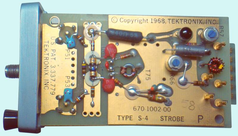
If the signal is periodic, then you can always use a sampling oscilloscope.

enter image description here

I mean, you can use any ADC provided its aperture window and jitter is small enough, but you asked for analog, so you gonna have to use the old diode bridge sampler like the wizards of old did...

DC-14 GHz with hand soldered thru-hole parts.

enter image description here

Check the date, 1968 ;)

\$\endgroup\$
5
\$\begingroup\$

Other than firing a rocket that travels at half the speed of light and so stretches out the received signal, you need something that stores a sample of what you receive and then plays it back at a slower rate. Ultimately this means you never catch up with what was originally transmitted i.e. you have to store and play back at a slower rate. An analogue tape does this just fine but if you want this in IC form then digital storage methods are the best way.

\$\endgroup\$
5
  • 2
    \$\begingroup\$ Right it would violate conservation of something, because buildup of incoming information :-) \$\endgroup\$
    – vicatcu
    Commented Aug 28, 2017 at 16:21
  • \$\begingroup\$ I can't tell if I'm missing some relativistic effect or if you just meant to type half the speed of sound. \$\endgroup\$
    – jalalipop
    Commented Aug 28, 2017 at 17:00
  • 2
    \$\begingroup\$ @jalalipop: I think he is alluding to red/blueshift (doppler effect). \$\endgroup\$
    – jbord39
    Commented Aug 28, 2017 at 17:03
  • \$\begingroup\$ I am alluding to that. \$\endgroup\$
    – Andy aka
    Commented Aug 28, 2017 at 17:16
  • 4
    \$\begingroup\$ Oops. So was I, but for some reason I reason I was assuming a sound wave. I've got RF hardware running on my desk yet I forgot that EM waves exist, doh \$\endgroup\$
    – jalalipop
    Commented Aug 28, 2017 at 20:28
3
\$\begingroup\$

There is a way to do this: 'chirped' laser pulses and dispersion compensation fiber. The refractive index of fiber (and hence the speed at which light propagates down said fiber) is a function of the wavelength of light. This is called dispersion as it results in narrow pulses dispersing out in time. Dispersion compensation fiber is designed to have very high negative dispersion such that it can 'undo' the dispersion of a much longer length of normal fiber.

Start with a chirped laser pulse that sweeps in wavelength. This can be generated by taking a very narrow, wideband pulse and sending it through a length of dispersion compensation fiber. Then amplitude modulate the chirped pulse with the signal you want to stretch. Then send the modulated pulse through a nice long piece of dispersion compensation fiber.

This is really a technique for very short timescales, requiring several km of dispersion compensation fiber to stretch pulses of a few 10s of ns. Dispersion in dispersion compensation fiber is usually on the order of -50 ps/nm/km.

\$\endgroup\$
3
  • 1
    \$\begingroup\$ Cute ... but care to put a length on the fibre you'd need to get, say, a millisecond of dispersion? \$\endgroup\$
    – user16324
    Commented Aug 28, 2017 at 21:14
  • 1
    \$\begingroup\$ This has no relevance to the question at all. "Chirping" will convert a short-duration wideband pulse into a signal that has a smaller peak-to-average value (and back again), but it won't time-compress an arbitrary signal in any recoverable way. If you try to AM the chirped pulse, the compensation fiber will turn this into a narrow waveform in which the actual information is encoded in the "noise" that comes before and after the main pulse. Not at all useful for TDM. \$\endgroup\$
    – Dave Tweed
    Commented Aug 28, 2017 at 22:21
  • 2
    \$\begingroup\$ This is actually a real technique that has a number of applications, see en.wikipedia.org/wiki/Time_stretch_analog-to-digital_converter , en.wikipedia.org/wiki/Serial_time-encoded_amplified_microscopy \$\endgroup\$ Commented Aug 29, 2017 at 0:54
2
\$\begingroup\$

There's really no connection to TDM. Although the PSTN was digital before TDM was adopted, the same concept works with analog samples.

You just need to pick a sample rate that captures the information you want. Continuing with the PSTN example, that would be a sample rate of 8000 Hz, which captures audio falling in the range of 300-3400 Hz.

To interleave N voice channels, you need a communications channel that can handle 8000 × N samples/second. You send one sample from each of the voice channels, in succession, and then start the whole sequence over again 1/8000 second (125 µs) later.

You can either sample all of the voice channels simultaneously and then delay the samples by some fraction of 125 µs according to their channel number, or you can simply shift the phase of the sampling for each channel to begin with (which is what most PSTN equipment does).

The bottom line is, there's no need for "time compression" if the TDM frame rate matches the sample rate required for the individual channels.

\$\endgroup\$
2
\$\begingroup\$

This really can't be done analog. While people have thrown out a bunch of neat and interesting ideas, passive analog circuits can only (1) shift phase and (2) attenuate. Everything they can do is limited to this, which can be expressed mathematically by the transfer function (which will multiply all information in frequency domain by a complex function that both shifts the angle and attenuates the amplitude).

If you go for amplification as an analog active addition, obviously you can also boost some frequencies - but really that is all you get that is more.

There are ideas like bucket brigades, but as noted this is really going digital (or at least quasi-digital). In the old days, the idea of recording on one speed on tape and playing back at half speed is really the only practical approach.

This sort of thing is much easier to do digitally. Even there, however, you need to be clear about what you want. If you want to start at t=0 and stretch a signal that goes to t=1 and get it to come out over twice the time at the same initial time (so, output 0

\$\endgroup\$
5
  • 3
    \$\begingroup\$ Note that "analog" does not necessarily imply LTI (linear, time-invariant). Your statements apply to the latter, not the former. \$\endgroup\$
    – Dave Tweed
    Commented Aug 28, 2017 at 22:30
  • 1
    \$\begingroup\$ You look like you posted part-way through a sentence. \$\endgroup\$
    – wizzwizz4
    Commented Aug 29, 2017 at 6:02
  • 1
    \$\begingroup\$ @DaveTweed: He said passive analog components. Transistors are generally considered active, right? I suppose at a small enough scale pretty much anything will weird behavior, but for practical purposes is he correct about passive components having this limitation? \$\endgroup\$
    – user541686
    Commented Aug 29, 2017 at 8:09
  • 1
    \$\begingroup\$ Sampled data implies neither digital nor "quasi-digital" (whatever that means). Even though it is true that the vast majority of digital systems are sampled data systems, the reverse is not necessarily true. And the question contained no constriction to passive components. \$\endgroup\$
    – user16324
    Commented Aug 29, 2017 at 10:36
  • \$\begingroup\$ Yes to Dave Tweed. In most cases, when people think of things like this, thought, it is a 'smooth' stretching or some such. And they are hoping to do it with a classical circuit. I glossed over ideas that are not LTI since LTI gives the real intuition. \$\endgroup\$
    – eSurfsnake
    Commented Sep 12, 2017 at 19:29
1
\$\begingroup\$

It seems that you are providing the best answer yourself. You state, "It's straight forward to do in a computer." All you need then, is an "appropriate" A-D converter to feed the signal to the computer, and then a D-A converter to give you the final signal. The computer will give you all the flexibility you might need to process the signal.

\$\endgroup\$

Not the answer you're looking for? Browse other questions tagged or ask your own question.