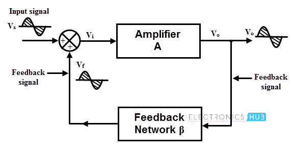
Perhaps that is not worded properly. But what I am wondering is given the picture below lets assume I have a 1V sinusoidal input and that the amplifier in turn gives me a 10V sinusoidal, then the feedback will attenuate that back to 1/10 of the output to give me again 1V so that it can be converted back up to 10V. But if my input is already at 1V whats the point of the feed back? Unless you add the input to initialize it and then take it away and let the oscillator oscillate on its own.
-
2\$\begingroup\$ The depiction shows an amplifier with feedback, but you are asking about oscillator, which is not the same. \$\endgroup\$– Marko BuršičCommented Sep 16, 2017 at 18:08
-
\$\begingroup\$ This is a poor block diagram showing non-inverted signals and two + inputs to a mixer symbol. Very improper. \$\endgroup\$– D.A.S.Commented Sep 16, 2017 at 19:06
2 Answers
As your last sentence says, the input is only to initialize it, when first learning of the principles of many kinds of oscilators, we assume an imput signal.
In practice this input signal comes from any kind of electric signal ( noise, radiation) that can induce the system to oscilation. After that initial state we assume that its removed.
PLL
This block diagram is a PLL or Phase Locked Loop.
It multiplies the frequencies ( to get sum and difference f then with a LPF rejects the sum frequency products) to obtain a phase error as a DC voltage to control a VCO and the H feedback could contain dividers or fraction N dividers, so discussion of ac voltage is then irrelevant to the transfer function but perhaps the answer needed for this question and your understanding.
Depending on the LPF bandwidth and loop gain, the phase error can include a frequency error with sufficient capture range to pull the VCO to produce only phase error. The Filter is a tradeoff between jitter and frequency error capture range and lock time.
Negative Feedback Loop
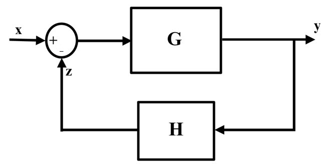
Here is a block diagram for a control system using negative feedback. Similar to the above only due to the inversion of phase error with a positive VCO.
The x in a circle is used as a multiplier and the phase error is such that the voltage is inverted to create a negative feedback loop.
Below it is a circle used as a differential amplifier with polarity signs.
Here the feedback is subtracted (Negative feedback). G could be low but is often high gain ( like 100 to 10 million) and then the overall gain y/x results from the difference of Y=(X-Z) * G where Gin=X-Z and output is Gin * G.
So the ratio or gain is Y/X = G/(1+GH)
So the open loop gain G is very large ( such as in Op Amps ) , the closed loop gain is practically 1/H.
-
\$\begingroup\$ That diagram posted by the original is for an oscillator but your diagram is about negative feedback amplifier. Why not consider it as an oscillator? \$\endgroup\$– emnhaCommented Sep 17, 2017 at 4:05
-
\$\begingroup\$ @anhnha does it look acceptable now? \$\endgroup\$– D.A.S.Commented Sep 17, 2017 at 20:55


