2
\$\begingroup\$

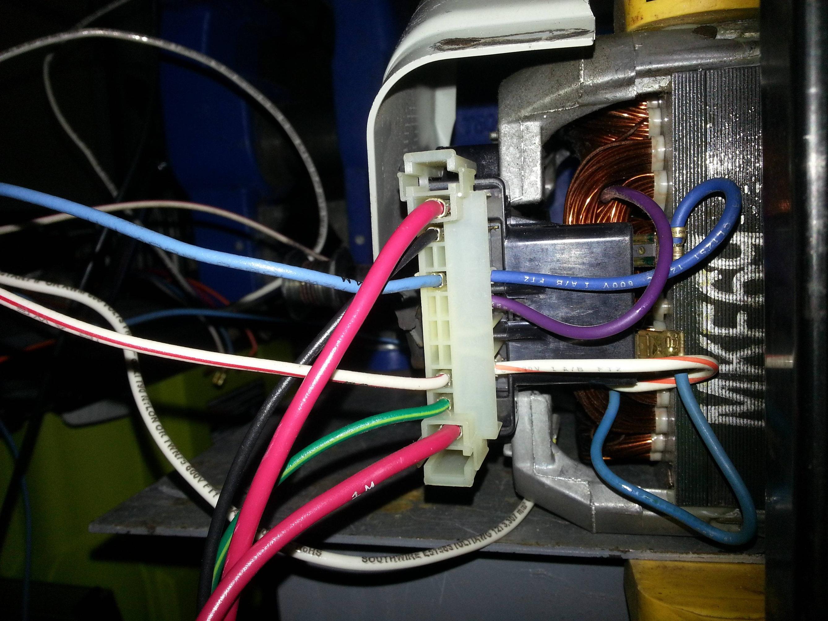
I have a Whirlpool dryer motor (model number S58NXMKE-6674 or part number: 3395652.) Image below:

Numbers

This is a type of universal motor that uses an electromagnet instead of a permanent magnet in the stator region.

I have a hypothesis that I may be wiring this device improperly. I've also observed a curious thing. When using an ohmmeter to measure the resistance between the two red wires (which I assume are for the brushes giver their larger diameter) I get an overload condition, indicating non-continuity.

I have a picture of what the wiring situation looks like below:

Wiring

Using the multimeter's connectivity mode I've determined that the black wire is not connected to anything, and that the bright green wire on the bottom is the case's ground connection.

This just leaves the two large red wires (which I believe were directly wired to the 120 V; one was wired to the mode selector switch I think), and the two smaller wires (the sky blue one, and the white one) which I believe are the field coils.

What is the proper wiring for this? I've assumed that the two red wires are for the brushes and tried a wiring scheme of (all are series connections): Hot wire -> red wire 0, red wire 1 -> field winding 0, field winding 1 -> neutral.

When I flipped the switch, nothing happened and my clamp on multimeter read 0 A when clamped just on the hot wire. Granted I was using 120 V, but I would have expected a burst of 12 A or so and for the motor to start spinning; this didn't happen.

Is the black wire relevant somehow, or is it just used for a computer to manage speed or RPM or stats or something like that? What is the correct wiring for this type of motor?

Edit 0: Judging from the comments this is almost certainly an induction motor without a capacitor. I'll retry it with a new setup tomorrow.

\$\endgroup\$
14
  • \$\begingroup\$ the 115/600 marking on the label makes me assume it's a 120V motor rather than a 240V one. \$\endgroup\$ Commented Sep 17, 2017 at 21:47
  • \$\begingroup\$ @ratchetfreak You're probably right lol, I changed the post. \$\endgroup\$ Commented Sep 17, 2017 at 21:48
  • 1
    \$\begingroup\$ There will be a main winding, a start winding, and a centrifugal switch. That black thing is a microswitch (relay) that de-energizes the start winding once the motor is at full speed. The red wires may actually be for the heating element. In electric dryers, the heating element is disabled until the motor is running at full speed. I learned all this from a youtube video. \$\endgroup\$
    – user57037
    Commented Sep 17, 2017 at 22:37
  • 3
    \$\begingroup\$ I would expect this to be an induction motor rather than a universal motor. The auxiliary winding of a single-phase induction motor usually has a capacitor connected in series either all the time or just for starting. Dryers usually have a diagram on the back of the machine. If you don't have the whole machine, try to find a diagram online. \$\endgroup\$
    – user80875
    Commented Sep 17, 2017 at 22:37
  • 2
    \$\begingroup\$ A universal motor has the armature connected in series with the field. The same current flows through both. They would not have two different wire sizes. If a motor that is as open as the picture shows the commutator or brushes should be easy to see if the motor has them. \$\endgroup\$
    – user80875
    Commented Sep 18, 2017 at 2:33

5 Answers 5

2
\$\begingroup\$

The motor circuit is probably something like the following diagram. The start circuit could include a centrifugal switch that opens when the motor reaches full speed. It may or may not include a series capacitor. It could be contained in an electronic control module. If there is a centrifugal switch it may have more than one contact. One contact may enable the heating when the motor reaches full speed. Manufacturers sometimes change configurations without changing the model number of the dryer. A replacement motor for a given dryer may not be the same as the original motor.

enter image description here

\$\endgroup\$
2
\$\begingroup\$

The two large red wires are part of the heating circuit and have nothing to do with the motor windings... when the centrifugal switch closes it connects those two red wires which allows the heating circuit to run... it’s a safety against running the heater with the motor off.... if you look inside the metal cage on the end with the plug connector you’ll see the centrifugal switch mechanism.. there will be a plastic disc about 1-2 inches in diameter with a beveled edge.. if you slide it slightly along the shaft it will trip the centrifugal switch and allow you to better test circuit paths through the motor... alternatively look up whirlpool dryer wiring diagrams.... these motors are pretty identical across all models... also they’re all gonna be 110 even in a 220 dryer... it uses line 1 to run the motor and only the heating element gets line 1 running into line 2... typically line 2 is run across those large red lines to power down the heater when the dryer is off... on a gas dryer it just interrupts the 110 to the heater ignition circuit...

Edit: It should not need a start capacitor, the motor turns the drum with a belt, on the motor side it has a small 1 inch diameter pulley, on the drum side it wraps around the entire drum so it does not need a whole lot of starting torque...

Also you can take the cover off of that connector compartment and get an idea for how the centrifugal switch affects the contacts, the switching mechanism is entirely within that box...

\$\endgroup\$
1
\$\begingroup\$

Yes it does have a start Capacitor and Start windings. The 2 big wires are hooked to a series switch in the heater circuit. Can be used to turn on and off other equipment if needed, otherwise forget them. The switch is operated by centrifugal force. The switch also takes the start capacitor out and puts power to the purple run winding wire. So all you need to do is connect the hot side 120v line to the Blue wire. Neutral White line to White wire. and away it goes. The Black wire is also switched and lets the dryer know the motor and heating element are "on". Don't forget to connect the Green Ground wire as this a non-insolated situation. Remember open motors are DANGERIOUS!!

\$\endgroup\$
0
\$\begingroup\$

One of the red wires goes to the heating element the other goes to the internal bias thermostat.... I have this motor on my dryer and I am trying to figure out how to check the centrifrugal switch in it

\$\endgroup\$
0
\$\begingroup\$

The motor has a start winding (no capacitor).

Here's the schematic.

enter image description here

\$\endgroup\$

Your Answer

By clicking “Post Your Answer”, you agree to our terms of service and acknowledge you have read our privacy policy.

Not the answer you're looking for? Browse other questions tagged or ask your own question.