3
\$\begingroup\$

I'm trying to design a circuit to convert a 50 MHz clock source from 5 V to 3.3 V. At first, I thought of using Sparkfun's level translator shown in the link below:

https://learn.sparkfun.com/tutorials/bi-directional-logic-level-converter-hookup-guide

However, the NMOS used there, the BSS138, has delay and rise times that are unsuitable for the 50 MHz clock signal. It has a delay time of 2.5 ns and a rise time of 9 ns when turning on. Similarly, it has a 20 ns delay and a 7 ns fall time when turning off.

I tried to look for solutions that are similar to the converter, but most of them don't seem to be suited for MHz signals. Some solutions show using ICs such as the SN74LVC8T245, but it's direction depends on the input to the direction pin, and the rise times seem unsuitable given the clock signal. Other solutions such as a resistor divider seem to work for lower frequencies, but I want to ensure signal integrity as this is a clock signal. Using a faster NMOS would be ideal and simplistic, and I can replicate the Sparkfun circuit for multiple lines, but what other solutions would be optimal for this fast clock signal?

EDIT: Since there has been some discussion regarding the need for bi-directionalaity, I wanted to explain a bit here. Initially, we thought that we could go with the level translator. One channel would be available for shifting the clock from 5 to 3.3 V, and the remaining channels would be used as needed for other purposes. But, due to the specs of the BSS138, it didn't seem reliable for our 50 MHz clock. After some discussion, being bi-directional is no longer a requirement, at least for the clock signal, so we're just focusing on shifting the clock down for now. I'm really sorry about mentioning bi-direction. Let's just forget about it for now. We plan for the clock signal to be stepped down, and then it should go into another module that accepts 3.3 V as an input. I don't know the load capacitance or impedance of the module, but when I find that out, I'll update here accordingly.

EDIT: So, after ignoring the bi-directional functionality, I think I may have found a potential solution: to use a buffer to step it down from 5V to 3.3 V while keeping signal integrity. I found some buffers that seem to work from TI, the SN74LV1T34 and the SN74LV1T126.

http://www.ti.com/product/SN74LV1T34/description

http://www.ti.com/product/SN74LV1T126/description

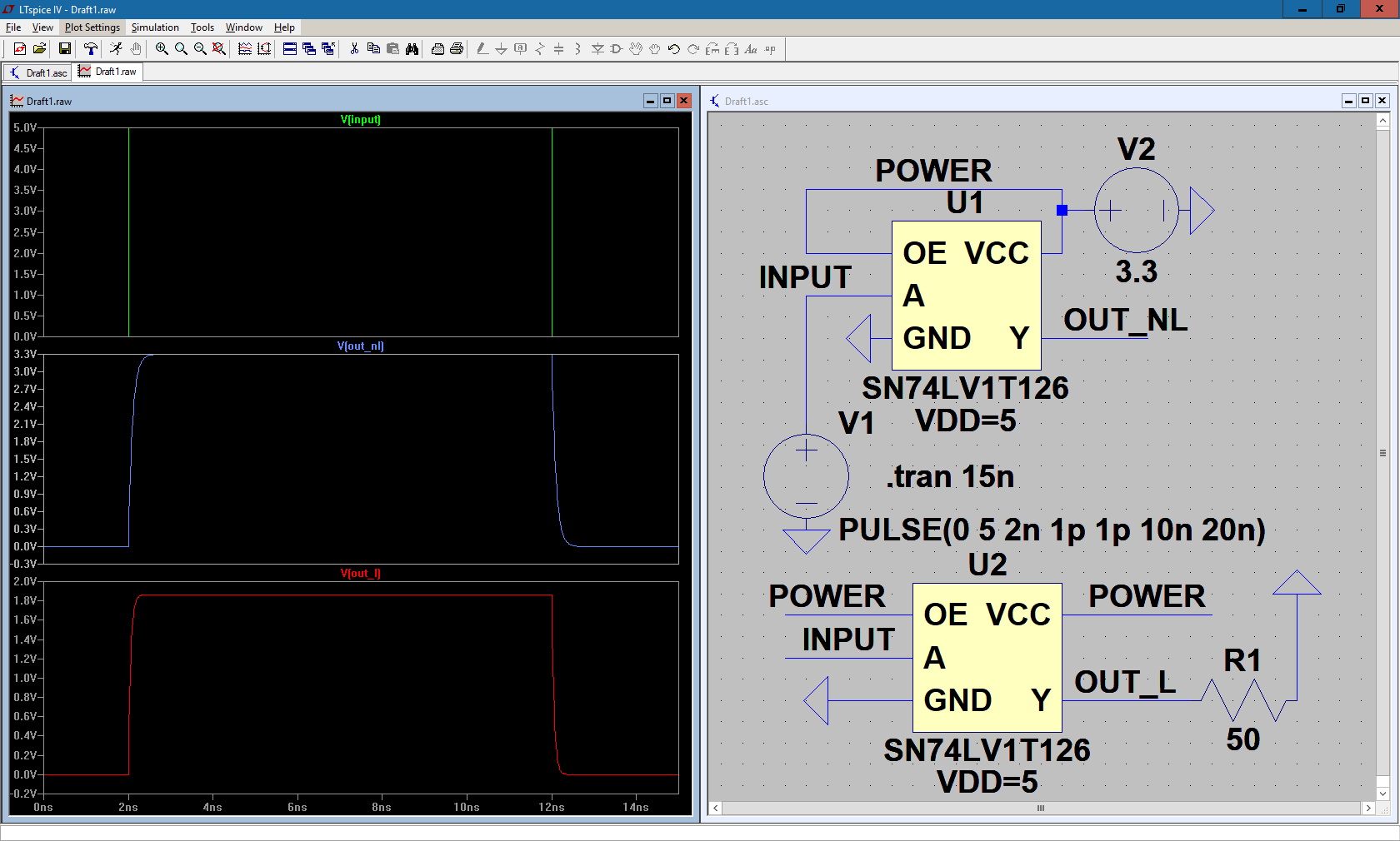
I imported the model of the SN74LV1T126 into LTspice and ran a simulation, hooking it up to 3.3 V and a 50 MHz 5-volt clock source, showing the output voltage with and without a load. Ideally, I would have liked to test out the SN74LV1T34, but there are no SPICE models available for it, so I'm just working with the SN74LV1T126. The image is shown below:

Logic Level Sim 1

Here, I'm just showing one clock cycle so that I can measure the rise and fall times to see if it is within acceptable tolerances given the clock input. Judging by the sim, it seems to work well, but when under a load, it doesn't reach 3.3 V, but rather it falls down to 1.8 V. Since this is going to be hooked up to a module, it will be under load, so is there anything I can do to ensure it reaches the correct voltage?

\$\endgroup\$
18
  • 11
    \$\begingroup\$ If you have "clock source", why your level-shifting circuit needs to be "bi-directional"? \$\endgroup\$ Commented Sep 18, 2017 at 21:48
  • \$\begingroup\$ farnell.com/datasheets/… \$\endgroup\$ Commented Sep 18, 2017 at 21:59
  • 3
    \$\begingroup\$ Maybe I'm not following your future proof concept, not knowing what the project entails and all, but if you are worried about needing it at 5V again, well then you could just take it directly from the source... \$\endgroup\$ Commented Sep 18, 2017 at 22:21
  • 5
    \$\begingroup\$ @user101402 that is kind of a silly requirement. One doesn't later change the clocking on a hunch. That will require relevant redesign anyway. \$\endgroup\$ Commented Sep 19, 2017 at 0:50
  • 1
    \$\begingroup\$ What makes you think 50MHz bi-directional level shifter is even possible? The current state of the art by Maxim this year is (not 16) but 8 MHz and I2C limit is 3.2MHz. DO you know why there is a limit? \$\endgroup\$
    – D.A.S.
    Commented Sep 19, 2017 at 1:17

2 Answers 2

1
\$\begingroup\$

If you think you can suddenly jump from a speed limit of 3.2MHz for I2C speed3 to 50MHz without impedance control on drivers on both sides , careful shielding and controlled T-line impedance with a low RdsOn open-drain switch that rises in Coss, Ciss as RdsOn is reduced.

Line driver load RC time constants rule the maximum speed

  • when you dont follow controlled impedance lines.

Here is the fastest one at 16 8 MHz that I found. (2017) with Nch FETs

https://datasheets.maximintegrated.com/en/ds/MAX14591.pdf

But in BJT series switches one can get <3.3ns max rise\fall times into 300 Ohm loads= 30pF using the PCA3060 suggested by @BruceAbbot

However even this may not work on I2C at 50 MHz

The PCA9306 has a standard open−collector configuration of the I2C−bus. The size of these pull−up resistors depends on the system, but each side of the translator must have a pull−up resistor. The device is designed to work with Standard−mode, Fast−mode and Fast mode Plus I2C−bus devices in addition to SMBus devices.

The maximum frequency is dependent on the RC timeconstant, but generally supports > 2 MHz

  • but The maximum frequency is totally dependent upon the specifics of the application and the device can operate > 33 MHz. Basically, the PCA9306 behaves like a wire with the additional characteristics of transistor device physics and should be capable of performing at higher frequencies if used correctly Let's consider non-bidirectional clock and data buffers level shifters first.

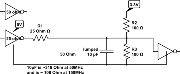
This is one approach using stripline= 50 ohms and 25 Ohm 5V logic 74LVC' or 74LVA' family.

schematic

simulate this circuit – Schematic created using CircuitLab

This is old school using 74ACL and 74ACL2 but works.


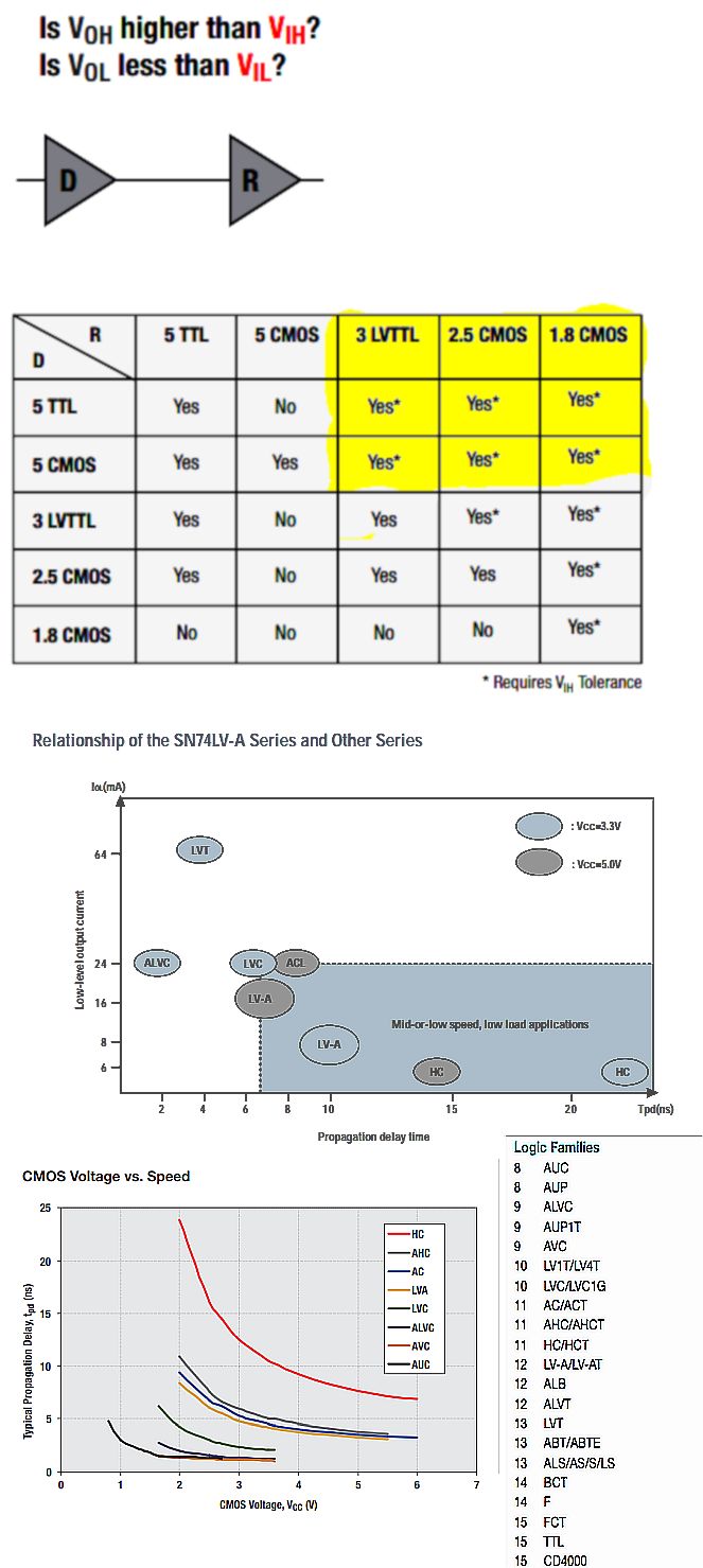
Now there are so many different logic families to consider that do NOT need level shifters for unidirectional signals.

enter image description here REF

  1. http://focus.ti.com/pdfs/logic/lvabrochure.pdf
  2. http://www.ti.com/lit/sg/sdyu001ab/sdyu001ab.pdf
\$\endgroup\$
14
  • \$\begingroup\$ How is this bidirectional? \$\endgroup\$
    – The Photon
    Commented Sep 19, 2017 at 0:10
  • \$\begingroup\$ LIke Ali said, why does a Clock have to be bidirectional Does it have to be tri-state too? \$\endgroup\$
    – D.A.S.
    Commented Sep 19, 2017 at 0:50
  • 1
    \$\begingroup\$ Why are you talking about I2C? What's 3.2 MHz got to do with anything? \$\endgroup\$
    – pipe
    Commented Sep 19, 2017 at 9:04
  • 1
    \$\begingroup\$ I'm sorry about the bi-directional requirement. After some thought, I'm just trying to have it go one-way right now. I looked at the PCA9306, and it seems that it would fit my needs due to the fast switching rise and fall times, so it seems that it would work for a 50 MHz signal. However, I'm attempting to find a model of it to test in LTspice, and TI's model is only in HSPICE. Also, where does 3.2 MHz have to do with anything? \$\endgroup\$ Commented Sep 19, 2017 at 12:49
  • 1
    \$\begingroup\$ just read the specs of 74LVCxxx parts like I suggested that accept 5Vin with low latency and unless you model the track impedance , load and stray capacitance, simulations are less useful \$\endgroup\$
    – D.A.S.
    Commented Sep 19, 2017 at 20:27
3
\$\begingroup\$

Well, while I do not understand the need for bidirectional (for a clock of all things?) there is one component that would seem to fit the bill...

Introducing the humble transformer!

Something like an FT50-61 with maybe 10 turns tapped at 6 and cap coupled in and out, dc restore with a couple of 220 ohm resistors, would seem to fit the bill.

Very standard fare in RF design, but possibly not that often seen on a logic board these days!

\$\endgroup\$
2
  • \$\begingroup\$ Thanks for your comment. I was just focused on FETs and ICs, that I never considered a transformer. In theory, a transformer would work, but I wouldn't think that you could just a transformer and have it step down from 5 to 3.3. What else would you have to add to a circuit to make it reliable? \$\endgroup\$ Commented Sep 19, 2017 at 12:26
  • \$\begingroup\$ user101402 has no idea about impedance control, unintended radiation for EMC, and has much to learn about design from books. \$\endgroup\$
    – D.A.S.
    Commented Sep 19, 2017 at 14:12

Your Answer

By clicking “Post Your Answer”, you agree to our terms of service and acknowledge you have read our privacy policy.

Not the answer you're looking for? Browse other questions tagged or ask your own question.