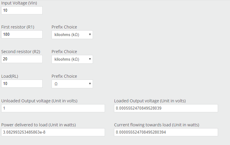
What, if any, are the pros and cons of using smaller or higher value resistors here? Why not go for much higher values - say, 360kΩ and 40kΩ - for even greater measurement precision?
The disadvantage of using high value resistors in a voltage divider is it makes the output impedance higher and hence makes the output voltage more sensitive to loading.
Lets run some approximate numbers.
At audio frequencies we can regard a coaxial cable as a capacitor.
You voltage divider has an output impedance of just under 20K.
A scope input in hi-z mode usually has an input impedance of 1 Megohm in paralell with low 10s of picofarads.RG58 coax has a capacitance of about 100pF per meter. Lets say you have a couple of meters of coax and say 250pF total for cable, scope, PCB traces etc.
So first lets look at the near-DC case. A 20K impedance driving a 1 Megohm load gives a gain error of about 2%.
What about higher frequencies? the output impedance of your voltage divider forms a RC filter with the capacitance of the cable/scope. The break frequeny of a RC filter is
$$f_c=\frac{1}{2\pi R C}=\frac{1}{2\pi * 20 * 10^3 * 250 * 10^{-12}}=\frac{1}{\pi * 10^5 * 10^3 * 10^{-12}} = \frac{1}{\pi * 10^{-4}} \approx 3000$$
That is a bit low for audio work. I would be wanting to knock those resistor values down significantly to bring the break frequency up. OTOH we don't want to knock them down too far or we run into power dissipation problems. We probablly want resistors about 20 times smaller than your values pushing the break frequency to somewhere around 60kHz.
Unfortunately 9K resistors aren't a standard value but we can form one by connecting a 4.3K in series with a 4.7K.
Note that 10x scope probes do use a very high value resistor, however they also use compensation capacitors that are tuned to match the characteristics of the cable and scope and in some cases special cables.
How careful do I need to be about the power ratings of R1 and R2? Am I correct in assuming that with the values I currently have, that the ratio of current going through the parallel branches is so tiny that even puny 1/4W resistors would barely be taxed?
You said you bought four 300W resistors. It's not clear to me if you plan to use them to build four seperate amplifier measurement circuits with one 300W resistor each or one big measurement circuit using all four. Lets assume the latter for now.
Your divider chain has a resistance of 200K which is 25000 times the resitance of the 8 ohm dummy load. So when 1200W is running through the dummy load resistors 0.048W is running through the divider chain. No problem.
My suggested chain has a resistance of 10K which is 1250 times the resistance of the 8 ohm dummy load. So when 1200W is running through the dummy load 0.96W is running through the divider chain. Of this 0.4512W is dissipated in the 4.7K resistor and less in the other resistors.
That seems like a workable design to me. 0.6W metal film resistors are readilly available and pretty cheap.


