2
\$\begingroup\$

TL,DR: Use a comparator, not an opamp. See Frosty's answer below.

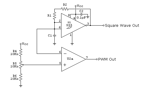
I'm trying to make a pulse waveform generator with variable duty cycle. The 555 timer is used to generate a sawtooth waveform, which is then compared to a constant voltage from a voltage divider. The schematic works in principle, but for some reason the output of the opamp has a very low slew rate.

This is the schematic:

enter image description here

Vcc is 5 volts. R1, R2 and C1 are such that the width of one tooth of the sawtooth waveform is roughly 200 microseconds (I'm seeing that with the scope). However it takes roughly 10 microseconds for the output of the opamp to go from 0 volts to 4 volts.

The opamp in question is TL072, which, according to its datasheet has a typical slew rate of 13V/us. There's also a graph that is showing "Normalized slew rate", which is roughly 1V/us at +/-15V power supply.

Am I misunderstanding what slew rate really is? Shouldn't this amplifier go from 0 to 4 volts in about 0.3 microseconds?

UPDATE: The circuit behaves as described with no load.

\$\endgroup\$
6
  • \$\begingroup\$ Slewrate depends on output capacitance. The slewrate given is with a 2kOhm resistor and 100pF capacitance. I don't know what your load is on the PWM out pin, but it could be the cause of the lower risetime. \$\endgroup\$
    – Joren Vaes
    Commented Sep 27, 2017 at 16:36
  • 1
    \$\begingroup\$ From DS: "(1) VCC+ and VCC– are not required to be of equal magnitude, provided that the total VCC (VCC+ – VCC–) is between 10 V and 30 V." If you only have a 5V rail, that's your problem \$\endgroup\$
    – sstobbe
    Commented Sep 27, 2017 at 16:37
  • \$\begingroup\$ Minimum supply voltage of TL072 is +/-5V (or 10V single supply). Also, it is not rail-to-rail so getting 4Vout with 5Vin is not realistic even if the chip could run at 5V. \$\endgroup\$
    – Frosty
    Commented Sep 27, 2017 at 16:38
  • 1
    \$\begingroup\$ In addition, you are using the opamp where you should be using a comparitor. The opamp is driving into saturation on each transition. You may be seeing some delay as it recovers. \$\endgroup\$
    – Transistor
    Commented Sep 27, 2017 at 16:38
  • 1
    \$\begingroup\$ @laptop2d from the pinout and circuit connection, definitely a 555. \$\endgroup\$
    – next-hack
    Commented Sep 27, 2017 at 16:58

1 Answer 1

4
\$\begingroup\$

There are several contributing factors to the poor performance of the circuit:

1. Insufficient supply voltage

Minimum Supply Voltage for the TL072 is listed as 10V. Using only 5V is well below this minimum.

2. Insufficient supply voltage headroom

The TL072 is not able to drive its output up/down to either voltage rail so expecting it to output 1V under Vcc is not realistic. See this question for more details.

3. Improper component selection

You should be using a comparator in this circuit and not an opamp. While the diagrams and basic function of an opamp and comparator are similar they are not substitutes. See this question for more information.

\$\endgroup\$
3
  • \$\begingroup\$ I've tried raising Vcc to 12V. So now it takes about 25us to reach the voltage of 10V. Looks like my biggest problem is item #3. Is the slew rate really so low because the opamp is being overly saturated? \$\endgroup\$ Commented Sep 27, 2017 at 20:35
  • \$\begingroup\$ How are you measuring your rise time? How long does it take to go from 0V -> 1V? \$\endgroup\$
    – Frosty
    Commented Sep 27, 2017 at 20:50
  • \$\begingroup\$ I see the waveform on my scope. It is a pulsed wave. As far as I see, the slopes are linear and symmetric, and not very steep. So going from 0V to 1V with Vcc=12V takes about 2.5us. \$\endgroup\$ Commented Sep 27, 2017 at 22:23

Your Answer

By clicking “Post Your Answer”, you agree to our terms of service and acknowledge you have read our privacy policy.

Not the answer you're looking for? Browse other questions tagged or ask your own question.