The CR2477 has over 3 times the capacity of the CR2302 so seems a better target battery for your project. You can draw many mA from the battery if you are willing to sacrifice long use times.
Even though you are measuring eye blinks it seems it would still be possible to use a sleep mode for your MCU and turn off the LED in the OPR5005 to reduce power consumption.
If you were to come out of MCU sleep at several hundred Hz, measure eyelid open/closed status (perhaps no more than 50-100 us on time) and go back to sleep you may be able to reduce your power by almost 100:1.
If you characterize the LED/phototransistor pair then you can find more accurately the current you need to run the LED at. Perhaps this may be closer to 10 mA than 20 mA (and any gain is worthwhile).
To deal with the pulse current drawn from the battery all you need is a large value capacitor across it. The battery keeps the capacitor fully charged and will supply current far beyond the 1 mA use to measure it's load longevity.
As an example folks use CR2302 with a LED strapped directly across them and get lifetimes of 10's hours even though it is a serious abuse of the battery.
Your power draw is essentially a constant current when on (dominated by the LED) so you can use a simple CC discharge form such as dV = (I*t)/C to work out the change in terminal voltage (here I'm simply ignoring the current from the battery, and initial conditions are fully charged C).
So for an MCU/LED on time of 1 ms and a terminal voltage change of say 0.2 V at 20 mA you need a minimum of 100 uf. I would fit the largest value capacitor you can across your battery given your limited space.
I assume in all of this you want to transfer the data from the (head mounted?) measuring platform to your PC. Spending most of your MCU time in sleep probably means losing your BT connection, but perhaps you can simply store the data locally for most of the time. On occasions, you could come out of sleep and power up the BT connection to transfer data.
I know it's not your chosen components, but I'd be tempted to use an NRF24L01+ in burst mode to transfer data. These are easy to initialize and provide a reliable link (retransmit) without needing connection oriented protocols.
For the MCU a small ATTiny85 might suffice, though I have no idea how much code you need to run in your MCU.
Update since Question edit....
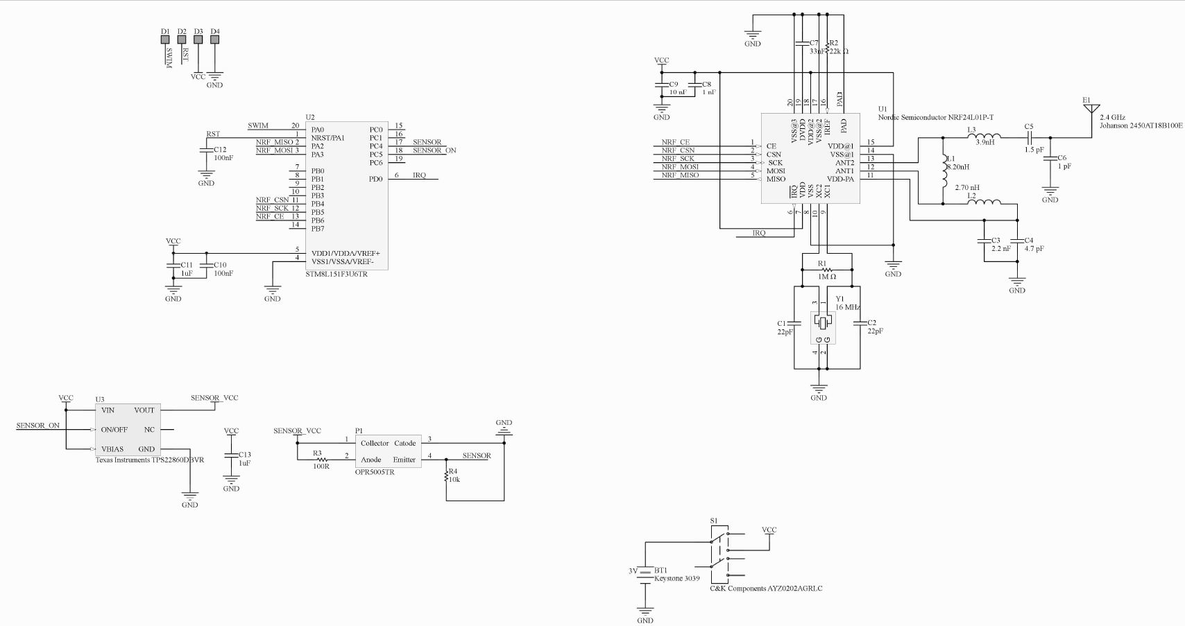
A much better attempt at a viable circuit.
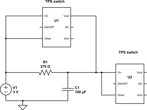
C13 should be 100 uf minimum with a series R of about 270 Ohms. This will ensure that the Vbatt is not held down or rises too slowly during initial turn-on.
The cap will take less than 100 ms to charge to a suitable voltage level, but will be at this level for the rest of the powered on time.
You could be even more creative and short out the series resistor with another TPS22860 once the cap is charge and after your initialization runs if you felt so inclined (this would share the sensor current more with the supply than otherwise).
Connect the sensor Collector to the sense GPIO with your pull-up resistor and connect the Emitter to ground. It does not need to be powered as an Emitter follower, and does not need to be switched on an off.
The OPR5005 does not need to be turned on for more than 500 us at maximum.
Let's assume that you come out of sleep every 10 ms (100 Hz), turn on the sensor for about 50 -100 us, sense the state of the eye-lid.
If the eye-lid is closed you could sleep for say 5 ms, or at the very least power down the sensor for 5 ms.
Next power-up or re-activation of the sensor do the same again. If the eye-lid is open (after having been closed) go back to 10 ms sleep state.

simulate this circuit – Schematic created using CircuitLab
You have a switch to turn your unit off/on (I did not show it here). With 100 uf direct across the battery supply and a high output resistance (relatively) battery the capacitance is enough to cause the supply voltage to rise slowly.
In the extreme it (as the battery is consumed and it's internal resistance rises) this may be enough to cause the MCU to misbehave on power up.
If both switches are off on power-up then the current to charge the cap is through the R1 resistor. When the cap is fully charged (you could use the A/D to test it perhaps?) then turn on the first switch, U1. Now when you turn on the second switch (U2) the R1 resistor is shorted (by U1) to share the sensor current from the cap and the battery.


