0
\$\begingroup\$

Level shifter with emitter follower and voltage divider

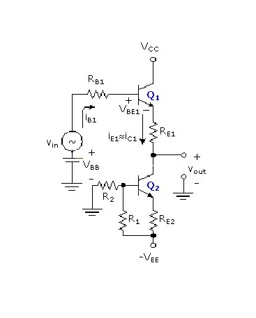
As we can see that input fed to this amplifier is the output of final stage of a multistage amplifier and if we apply KVL to base-emitter loop then KVL of Base-emitter loop

Vbb is the DC level acquired from the previous stage. Now, It is clear that the output of Q1 (emitter-follower) is less than (Vbb-Vbe1) here.I want to know What the importance and function of the Q2 constant current source are here. Further, it is also not clear to me that how the DC level of the previous stage gets shifted upwards and why we are trying to pull that down with the help of this level shifter circuit.

Please help me with the functioning of DC level shifters.

\$\endgroup\$
1
  • \$\begingroup\$ It is pretty easy to understand how a constant current through a known resistor value yields a fixed voltage drop across the resistor. Moving the base of \$Q_1\$ moves the emitter equally. Since the resistor is tied to the emitter and since it has a fixed voltage drop across it, the other side of the resistor will be a fixed voltage below the emitter, too. Simple shifter. But the reason why is left to the surroundings. If this is part of a DC coupled amplifier (no cap from Vout to the next stage), then the need for a shift might be clearer. But we don't know, since you don't say what follows. \$\endgroup\$
    – jonk
    Commented Oct 2, 2017 at 4:02

1 Answer 1

-1
\$\begingroup\$

Q2 is a CC sink = Ie1 = Ic2 from R ratios and Vbe2=0.7

If you set Vout=0 and compute Vbb to satisfy that, then Vout will follow Vin.

\$\endgroup\$

Your Answer

By clicking “Post Your Answer”, you agree to our terms of service and acknowledge you have read our privacy policy.

Not the answer you're looking for? Browse other questions tagged or ask your own question.