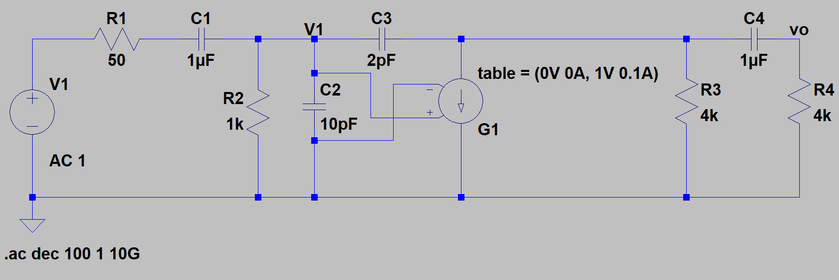
I'm trying to simulate a band-pass transconductance amplifier in LTSpice, which looks like this:
I used the recommendations of this post - https://electronics.stackexchange.com/a/278870/87695 - and used a G component with a table to represent the voltage controlled current source in my LTSpice schematic.
I have done some estimations on the locations of the poles and zeros:
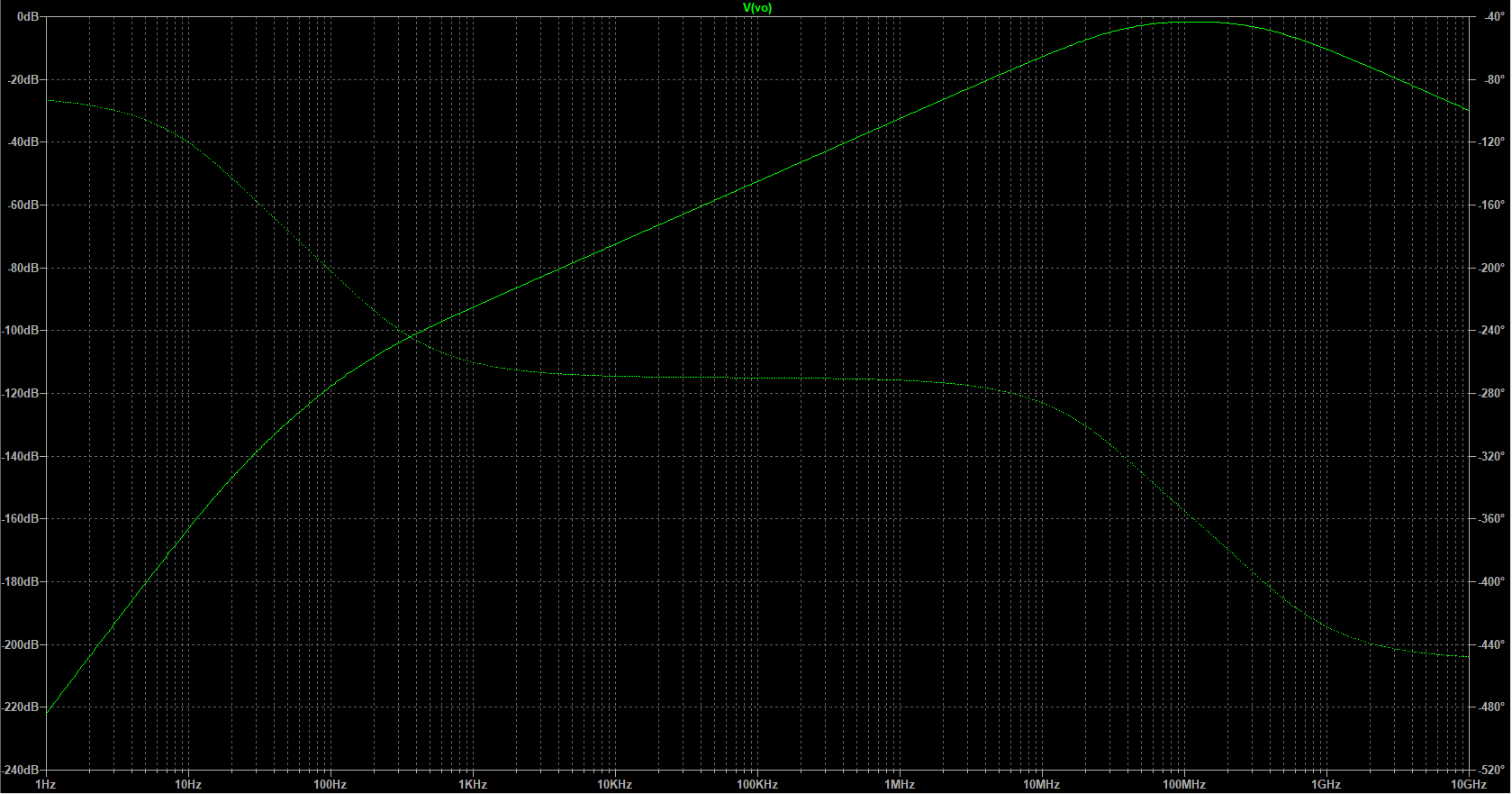
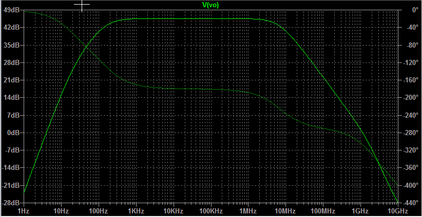
However, my simulation is not displaying the result I expect to see at all:
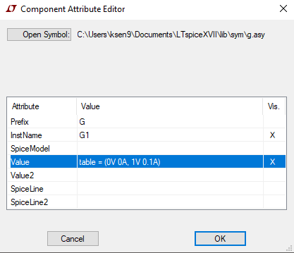
I suspect that I set up the voltage controlled current source incorrectly. Here are the parameters:
Any idea of what I did wrong? Thanks in advance.



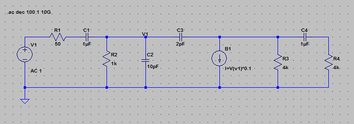
table(), so you can just replace the whole line with0.1. BTW, behavioural sources, while versatile, can prove sluggish the higher the numbers, and their dynamic range, both on y and x axis, are reduced. Using aGsource is the most accurate and fastest way to do it. Behavioural sources are good when there are more complicated expressions. \$\endgroup\$