3
\$\begingroup\$

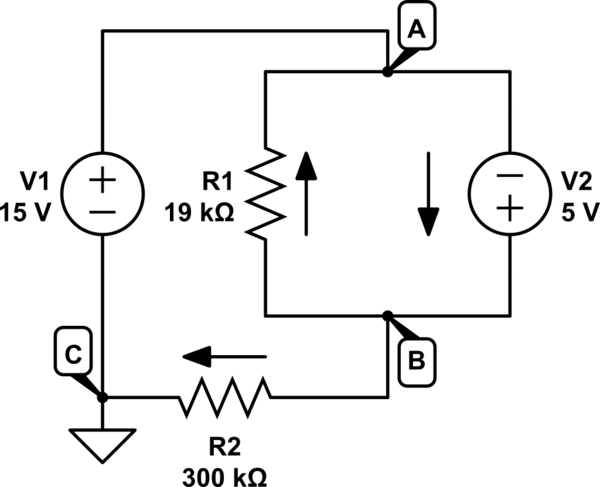
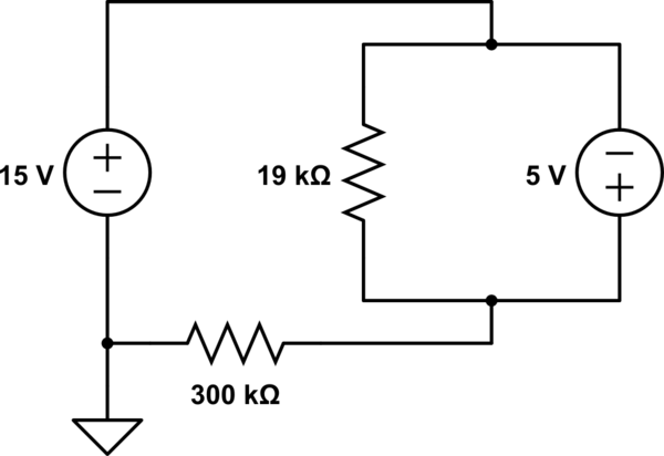
I am trying to solve the following simple circuit to obtain the current flowing through the 5V source. The answer I obtain does not agree with a simulator that I am using, and I think it's because I assume the wrong direction for current through the 19k resistor... Using conventional current flow, here is my approach to the problem:

Calculate the current through the 19k resistor as just 5V over 19k and I get 263uA. I then calculate the current through the 300k resistor as just 20V over 300k. I assume that the current is flowing in from the 5V source and also in from the 19k resistor and outward through the 300k resistor. Therefore using KCL I get:

(current through 19k) + (current through 5V) = current through 300k

263uA + I = 66.67uA

I = -196uA

However when I use the simulator at falstad.com/circuit/ I get a different result. I get like 329uA. Does it actually matter which direction I assume the current is flowing in? Or, is it that maybe the drop across the resistor is actually -5 because of the polarity on the voltage source?
schematic

simulate this circuit – Schematic created using CircuitLab

\$\endgroup\$
9
  • \$\begingroup\$ Well, first off you appear to be getting the magnitude wrong, regardless of your other question. As to the direction itself, it doesn't matter so long as you are completely consistent in your application. You should get magnitudes right, at least. You may want to communicate with others, though. So the adoption of "conventional current" would make sense when talking with others about your results. \$\endgroup\$
    – jonk
    Commented Oct 5, 2017 at 17:36
  • \$\begingroup\$ @jonk Updated, I mention that I am using conventional current flow to solve the problem. \$\endgroup\$
    – Snoop
    Commented Oct 5, 2017 at 17:41
  • \$\begingroup\$ You can't use KCL on this circuit. No matter what node you choose as ground, the voltage at the other nodes can be found by tracing paths through voltage sources, so KCL can't be applied. \$\endgroup\$
    – The Photon
    Commented Oct 5, 2017 at 17:41
  • \$\begingroup\$ What is the path for 300k ohm resistor current? \$\endgroup\$
    – G36
    Commented Oct 5, 2017 at 17:41
  • \$\begingroup\$ If you choose a ground node for your circuit and give the other nodes labels, it will be easier for us to discuss how to solve it. \$\endgroup\$
    – The Photon
    Commented Oct 5, 2017 at 17:42

5 Answers 5

1
\$\begingroup\$

Personally, I find it "singing to my mind" better when I take a moment to redraw a schematic.

schematic

simulate this circuit – Schematic created using CircuitLab
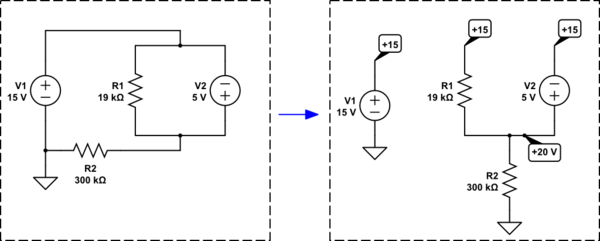
Do you see what I've done? It's the same circuit on the right. But I've removed some of the confusing wiring. Also, it's now perfectly clear that one of these nodes (wires) is at \$20\:\textrm{V}\$, too.

Now it is very easy to see what is happening. There is \$20\:\textrm{V}\$ across \$R_2\$. So you know the current in \$R_2\$. Also, there is \$5\:\textrm{V}\$ across \$R_1\$. So you know the current in \$R_1\$. Whatever is left over must be the current in \$V_2\$.

So,

$$\begin{align*} I_{V_2} &= I_{R_2} - I_{R_1}\\\\ &= \frac{20\:\textrm{V}}{R_2} - \frac{15\:\textrm{V}-20\:\textrm{V}}{R_2}\\\\ &= \frac{20\:\textrm{V}}{300\:\textrm{k}\Omega} - \frac{15\:\textrm{V}-20\:\textrm{V}}{19\:\textrm{k}\Omega}\\\\ &= 329.824561\:\mu\textrm{A} \end{align*}$$

I prefer simplifying my understanding of a problem before choosing a method for solving it by hand.

Of course, there are rigorous methods you must also learn to apply "by rote." Computer software in electronic simulators do this all day long. But when you are first learning these things, I think it helps a lot to try and redraw things to help "see" them better.

\$\endgroup\$
1
\$\begingroup\$

For conventional current we have this situation :

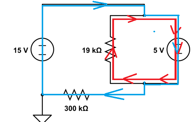
enter image description here

As you can see 5V source current is equal to blue current plus the red current.

\$\endgroup\$
3
  • \$\begingroup\$ Is that kind of like mesh analysis? \$\endgroup\$
    – Snoop
    Commented Oct 5, 2017 at 18:00
  • \$\begingroup\$ No, I just simply apply conventional current for the circuit. The 19k resistor sees 5V and 300k resistor will see 20V. Hence the current must flow. \$\endgroup\$
    – G36
    Commented Oct 5, 2017 at 18:06
  • \$\begingroup\$ @Snoopy Yes lets call the red current I1, from ohms law we know how big I1 is because it has 5V across a 19k resistor. Call the blue current I2 we know the voltage across the 300k resistor so again we know I2 by ohms law. And as we can see the current in the 5V source is I1+I2. Some people like to look at current loops, I prefer to look at currents in individual wires or traces but either method works. I'm also up-voting this answer as its clear. \$\endgroup\$ Commented Oct 5, 2017 at 18:07
0
\$\begingroup\$

Therefore using KCL I get

This circuit isn't a good candidate for KCL. Using KCL, when there's a voltage source connected to a node you have to form a supernode with the other side of the voltage source.

It would be easier to solve this circuit using KVL, or simply by inspection.

By inspection:

From your ground node, the node on the other side of the 15 V supply is at 15 V. I'll call that node "A".

From node A, the node at the other end of the 5 V supply is at 20 V. I'll call that node "B".

Now you can get the current through the 300 kohm resistor (from right to left) as simply 20 V / 300 kohm.

You can get the current through the 19 kohm resistor (from top to bottom) as simply -5 V / 19 kohms.

\$\endgroup\$
2
  • \$\begingroup\$ Just because you form a super-node means you can't use KCL? I don't get it. \$\endgroup\$
    – Snoop
    Commented Oct 5, 2017 at 18:00
  • \$\begingroup\$ @Snoopy, the problem in this circuit is that all the nodes form supernodes with the ground node. There are no independent nodes to use to find the circuit solution by KCL. Having found the node voltages and resistor currents by inspection, you can still find the currents through the sources by KCL. \$\endgroup\$
    – The Photon
    Commented Oct 5, 2017 at 18:23
0
\$\begingroup\$

You got the first two steps right, but then didn't add the currents properly.

Yes, the current thru the 19 kΩ resistor is (5 V)/(19 kΩ) = 263 µA, and the current thru the 300 kΩ resistor is (20 V)/(300 kΩ) = 67 µA.

With the 300 kΩ resistor open, the current thru the 5 V source is only due to the 19 kΩ resistor. With the 300 kΩ resistor connected, its current adds to what is flowing thru the 5 V source. The current thru the 19 kΩ resistor can't change since the voltage across it stays the same, by definition of what the 5 V source does. All the additional current from the external circuit can only flow thru the 5 V source.

The total current that the 5 V source is sourcing is therefore 330 µA.

\$\endgroup\$
2
  • \$\begingroup\$ A bit confused how you can get any current with the 300k resistor open. Would there still be a ground somewhere? \$\endgroup\$
    – Snoop
    Commented Oct 5, 2017 at 17:56
  • \$\begingroup\$ @Snoop: With the 300 k resistor open, I'm only talking about the current thru the other resistor. \$\endgroup\$ Commented Oct 5, 2017 at 18:00
0
\$\begingroup\$

schematic

simulate this circuit – Schematic created using CircuitLab
$$V_{BC} = V_1 + V_2 = 15V + 5V = 20V$$ $$I_{BC} = \frac{20}{300k}A \approx 66.7uA$$ $$I_{BA} = \frac{5}{19k}A \approx 263uA$$ $$I_{2} = I_{BC} + I_{BA} \approx 330uA$$

You assumed wrong the verse of the currents. Check in the figure above the positive direction of the currents involved.

\$\endgroup\$

Your Answer

By clicking “Post Your Answer”, you agree to our terms of service and acknowledge you have read our privacy policy.

Not the answer you're looking for? Browse other questions tagged or ask your own question.