1
\$\begingroup\$

I am using a raspberry pi in one of the systems that I am designing.The High output of raspberry pi IO pins is 3.3V . I want to generate a simple square wave pulse output on one of the IO pins on raspberry pi. However the square wave needs to be of 5V amplitude. Now I wish to make a simple circuit to do the same(Circuit attached)

Note- Voltage Level converter is UNIdirectional and Max frequency of switching is roughly 33kHz Transistor : BC547 enter image description here This circuit is based on this answer : Logic Converter
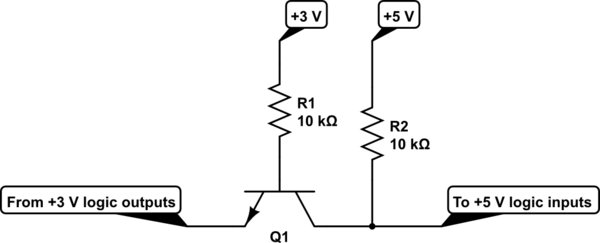
Questions:
1.Is BC547 used in moderately critical applications?can I/should I use any other slightly robust transistor? Kindly suggest if any
2.Should I add a diode at the output ?
3.Is BC547 ok in the given switching frequency range?

Thank you in advance !!

\$\endgroup\$
1

1 Answer 1

2
\$\begingroup\$

That circuit is a single-transistor bidirectional buffer. I would put a 1k-10k resistor between 3V3 and emitter as well, by the way. Note that this circuit should be used for comm lines that are kept high on idle (e.g. UART RX/TX).

If the speed is low enough (say, 57.6kBaud) then it will work. Input capacitances of the transmitter and receiver nodes play role as well.

PS: I'm using BC237/BC817 for low-distance (max. 3-meter-long) comms with speeds of under 100kHz.

\$\endgroup\$
7
  • \$\begingroup\$ Can't I use this circuit as a voltage level shifter(3.3v to 5v) if i ground the emmiter of the transistor? \$\endgroup\$
    – Mr.Sky
    Commented Oct 5, 2017 at 19:52
  • \$\begingroup\$ When a node wants to send a logic-one, it has to release the line by letting the output driver floating. And when a node wants to send a logic-zero, it has to pull the line to ground. That's why I said the last sentence of the 1st paragraph. If you ground the emitter then the transistor will turn on and it will pull the 5V side (collector) to ground. That is how a logic-zero is sent by 3v3-side actually. \$\endgroup\$ Commented Oct 5, 2017 at 20:00
  • \$\begingroup\$ ohh Ok now i get it but the gpios of raspberry pi i am using are kept low on idle(not like TX/RX). is there any quick fix in the circuit to make it work in this case? \$\endgroup\$
    – Mr.Sky
    Commented Oct 5, 2017 at 20:08
  • 1
    \$\begingroup\$ If you need 3v3 to 5V conversion only and if you're to use transistors then you'll need 2 transistors. Look at the circuit above. If you ground the emitter and connect R1 to raspberry pi output instead of 3v3 supply then you'll get a translated output from collector but the signal will be inverted (i.e. 0V when a logic-1 is sent). So you'll need one more copy of this inverter cascaded to the first stage to make the input and output in-phase. \$\endgroup\$ Commented Oct 5, 2017 at 20:17
  • 1
    \$\begingroup\$ That circuit shows what I said. So it'll work. \$\endgroup\$ Commented Oct 5, 2017 at 20:22

Your Answer

By clicking “Post Your Answer”, you agree to our terms of service and acknowledge you have read our privacy policy.

Not the answer you're looking for? Browse other questions tagged or ask your own question.