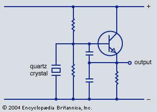
Your circuit is a Colpitt type oscillator in common collector configuration. Please note that a quartz can be (and is in practice) used in four different modes:
(1) series oscillation, (2) parallel oscillation, (3) high-Q inductor and (4) high-Q capacitor.
In the shown circuit, the quartz is used at a frequency where it works as a high-Q inductor. Thus, together with both capacitots it forms a parallel resonant circuit which has zero phase shift at the resonant frequency wo=1/SQRT(LC) with C=C1C2/(C1+C2).
This allows oscillation at the frequency wo - together with a common-collector stage - because the loop gain has zero phase shift.
Comment: Sometimes, you can find - for transistor-based oscillators - another explanation for the working principle: Negative-resistor oscillator. But explanation of the oscillation principle is - in this case - more complicated. Fortunately, every negative-resistor oscillator can be explained also based on feedback when we identify the corresponding feedback loop.
Note: The input resistance at the base is negative due to the positive feedback effect of the capacitor between base and emitter.

