2
\$\begingroup\$

I have a project that has 18 of these common-cathode displays, 36 digits in all, organized into three rows of 12 digits. My first version of the project used an Arduino and shift registers to drive them. I would shift out the 0th column of digits, latch them to provide power to the displays, then ground the 0th column. This would show the first character. Then, I'd shift out the next column of data, disable the ground on the 0th column, latch the 1th column, and provide ground to the 1th column to show it to the user.

It works, but it has a couple issues. It's very, very, very dim. I can make it brighter by holding each display on a while longer, but it doesn't go very far, and you can sense the low refresh rate when you look at it. Also, if I have a column that have very few segments active, they draw all the current I'm supplying and that column ends up being much brighter than the rest.

I have a ton (would you say I have "a plethora?") of MAX-7219 LED controllers, but there's a snag: the LED controller assumes a maximum of 8 segments per cathode. I considered using one LED controller to drive half of the segments on 8 digits, and another controller for the other half. This would (probably) work - I'd just deactivate the display on the upper half and activate the lower, then reverse the process a few milliseconds later.

I really want the drawing to be fire-and-forget. I have to generate the data I'm displaying, and this takes time. During this time, I can't really be burning CPU, flopping the displays. (Technically, I could do the flopping in a timer, but I'd have to stop the timer while I shifted out new data, and that timer might interfere with the LedController library, as well as the serial communications I'm using to get the data from a GPS module, anyway.)

So, is there a way that I can shift out 36 digits worth of data and completely forget about it for 100-1000ms, leaving the work of driving the display to someone else's hardware? I've even considered having one arduino to process data, then transfer it, somehow, to three - or even six - other arduinos for display.

\$\endgroup\$
11
  • \$\begingroup\$ When doing this kind of work, you do NOT use library code. I've written software on a truly stupid 8051 core, using the C8051F061, that took in 16-bit ADC data at 1 MHz, processed the data in real-time, generated fast measurement results, and all the while also updated a display. I even wrote a multi-threaded O/S for it so the code was fairly clean, too. That darned device only has 1 DPTR, so copying blocks are painful! Are you seeking a product recommendation? Or are you looking to make this "fire and forget" thing. \$\endgroup\$
    – jonk
    Commented Oct 11, 2017 at 17:01
  • \$\begingroup\$ There are many ways to do this, which is acceptable really depends on your application and budget. \$\endgroup\$
    – Trevor_G
    Commented Oct 11, 2017 at 17:07
  • \$\begingroup\$ Also, do you mean you are using a display that has (2) 7-seg displays plus decimal points? Or are you using (2) of those fancy 16-seg digit things in the display? It's not clear to me. \$\endgroup\$
    – jonk
    Commented Oct 11, 2017 at 17:08
  • \$\begingroup\$ @Trevor I've found some controllers that will do the trick, ICM7245, for example, but they're around $20 EACH. I have 30 MAX7219s lying around and would like to figure out how to use them, if possible. I'm toying w/ the idea of using 2 7219s per 8 digits, and having a 555, and inverter, and a couple transistors to switch back and forth between them to display half of the character at a time. As long as the refresh rate of the 555 is far less than the switching frequency of the 7219s, it should work. I'll be experimenting with it as soon as my order of 555s and inverts arrives. =] \$\endgroup\$
    – user30997
    Commented Oct 12, 2017 at 18:14
  • \$\begingroup\$ @jonk The packages are two digits each, 16 segments per digit. 18 pins, two are cathodes that select which digit to display and the rest of the pins are assigned the same segment in both digits. \$\endgroup\$
    – user30997
    Commented Oct 12, 2017 at 18:16

2 Answers 2

1
\$\begingroup\$

Dimness and variable brightness might have two causes:

  • You're MUXing too many (36?).

  • Your LED current-limiting resistor(s) are in the COMMON leg, not in each of the LED legs.

Muxing more than about 8 requires the common-cathode pull-down switch to pull too much current, especially when all your digits are "8". A discrete N-channel MOSfet might be able to handle the current required of the common-cathode driver. You might consider daisy-chaining four shift registers and pushing it to nine MUX (4 x 9 array).

For the anodes, you might get away with HCMOS shift registers (HC164, HC595). Even so, it helps to start with efficient LED segments that give decent brightness @ 1mA DC. Shifts can be done quite fast, so that the time to shift five daisy-chained HC164 doesn't eat into the MUX period (which should loop faster than 30 per second, else it becomes optically annoying). You should still optimize the shifting code for speed. The basic shift-cell might look like this (do 9 more rows of this):

schematic

simulate this circuit – Schematic created using CircuitLab

Those nine MOSfets need a way to drive their gates. An HC595 might be used to drive the MOSfets, simply shifting a single "1" in a ring. You might need two HC595 to get the extra bit (to get a 9-bit shift register). It's tri-state output might be used to turn off all the LED's while you're shifting if interrupt routines take too long, or if background flicker is distracting: the 5k pull-down gate resistor will ensure that all MOSfets turn off.
That's a lot of wiring, and a lot of resistors. It'll likely cause some RFI: try to wire it all very compact.
All the shifting could be done as a background process - it doesn't need a timer and can easily be interrupted by your other peripherals so long as their handlers finish in a reasonable time. Consider using the watch-dog timer as the MUX timer (if you're short of timers), if it can be crudely set to about 3 ms.

\$\endgroup\$
1
\$\begingroup\$

As you can probably tell by now, there is no "accepted" method. It's a set of tradeoffs that only you are in the better position to work out. You just need to use your imagination.

I do not fully apprehend your situation. But you've written enough about it that I can offer a thought or two. I gather that you would like to use your MAX7219 devices. And you already have the displays you mentioned, as well.

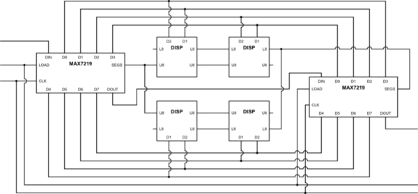
So something like this:

schematic

simulate this circuit – Schematic created using CircuitLab

One MAX7219 is used for the "upper half" of your displays. The other one is used for the "lower half." This gets full coverage for all your segments. The only other problem is the digit drives. For this situation, you activate both MAX7219 devices. However, if you imagine each 2-digit display as having four quadrants, then the upper-MAX7219 is driving the upper left quadrant while the lower-MAX7219 is driving the lower right quadrant. And then, in the next period, the upper-MAX7219 is driving the upper right quadrant while the lower-MAX7219 is driving the lower left quadrant. This keeps the cathode return currents separated. It takes two periods to complete one 2-digit display device. Eight periods covers four 2-digit displays, or 8 digits total, and does this with just two MAX7219 drivers using \$\frac{1}{8}\$ duty cycles.

You'll have to work out the dissipation issues, though. I've not bothered thinking about that part. Nor have I thought more about the average intensity you might get out of this, beyond what I already mentioned in comments.


If you want this to be "fire and forget," then you will need another microcontroller to operate this display for you. That's not a difficult task. But it adds another MCU and its associated software and hardware toolchain. And that can be a problem. But also an advantage. You'd just "download" the display data to it, letting it store that in its own RAM, and then just walk away until the next time you need to update that display data.

On the other hand, it's not difficult to set up a timer event on your current system that operates entirely "in the background." You can use your own software to "pre-prepare" all of the 8 states of data to transmit into 8 simple buffers (given the display data that needs to be displayed, first), which the timer event simply toggles between and then loops back over. The pre-preparing software can run in regular code at any time, completely independent of the display timer events. All it does is to set a "change message" that the timer event looks for in order to switch to the next set of 8 buffers, once it completes a prior display cycle, freeing up the memory for the last display data to be used by your code next time. ("Double buffering.")

Up to you.

\$\endgroup\$

Your Answer

By clicking “Post Your Answer”, you agree to our terms of service and acknowledge you have read our privacy policy.

Not the answer you're looking for? Browse other questions tagged or ask your own question.