1
\$\begingroup\$

I'm a freshman computer science major, and I still have a lot left to learn in the realm of circuitry, but I have a decent understanding of the fundamentals.

I have made an electric bike, and I wanted to install turn signals. The bike's battery is a 52 volt nominal, Lithium Ion battery (max 58 volts), so all my components must be able to operate on the voltage of this battery (unless I wanted to get a dc-dc converter to reduce to 12 volts, which I don't).

I installed a 60 volt solid state flasher relay to control the LED turn signals, but one problem is that the flasher doesn't allow the signal lights to flash completely on and off. Instead, they flash from 100 percent brightness to about 50 percent brightness. There appears to be some electricity leaking through the flasher. When I insert my body into the circuit, my own dry skin is enough of a conductor to light the LEDs to about 40 percent brightness. (Crazy huh?) So, the LED's apparently don't need very much electricity. Therefore, I expect it might be difficult to use a resistor to reduce the system power enough to prevent the LEDs from lighting at all when the flasher is "open." My knowledge of resistors is still limited, so any suggestions on this approach are appreciated.

Alternatively, my next idea was to use two electromechanical relays to completely break the circuit. I plan to control the energizing of the relays via my dashboard turn signal switch on my handlebars. Observe the following diagram (You'll have to forgive my circuit design skills):
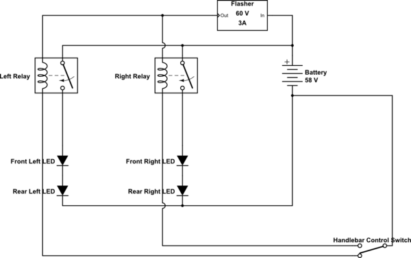
schematic

simulate this circuit – Schematic created using CircuitLab

Are there any flaws in this idea? Improvements? Will this work, given I get the right relays? If so, can you point me to the best relay for this (must handle up to 60 volts)?

Thanks!


LEDs:
.08 amps at full brightness
.02 amps at half brightness

Volts across flasher:
2 volts in "open" state
36 volts closed

Flasher Resistance:
512 Ohms with multimeter dial on "2000"

\$\endgroup\$
2
  • \$\begingroup\$ Welcome to EE.SE. You don't have to screengrab the CircuitLab circuits. They embed directly into your post (for free when you use the button on the editor toolbar) and we can copy, paste and modify them in our answers. Can you fix? Is there a datasheet for the flasher or can you reverse engineer it and draw a schematic? \$\endgroup\$
    – Transistor
    Commented Oct 23, 2017 at 17:50
  • \$\begingroup\$ Ok. I fixed the schematic. Thanks for the tip! \$\endgroup\$
    – micDropper
    Commented Oct 23, 2017 at 20:50

2 Answers 2

1
\$\begingroup\$

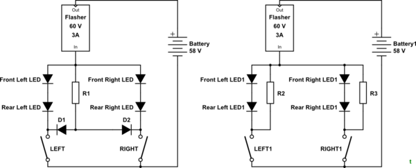
schematic

simulate this circuit – Schematic created using CircuitLab

Figure 1. Simple on-off control.

It's not clear why you think you need relays. They will probably add a nice clicking sound but you should be able to obtain complete isolation with the switches only.


OK. That's not going to work due to the leakage.

schematic

simulate this circuit

Figure 2. Adding a pair of diodes eliminates one of the relays.

How it works:

  • Switching on LEFT will cause the relay to turn on when current flows from the flasher through the coil and D1. D2 prevents the right LEDs from turning on simultaneously.

The problem is that a 60 V relay will require little current to energise it so you may find that the relay stays on and now you have LEDs at full brightness.

If you supply all the requested info and some details on the LED specifications there may be a workaround.


          LED current       Voltage drop across flasher
On        80 mA              2 V
"Off"     20 mA             36 V

From those numbers appears that your flasher passes about 20 mA when off. This is required to power the internal circuitry and on a 3 A load is < 1% so it wouldn't be noticed. On your 80 mA load it is passing 25% of the "on" current.

Solutions:

  • Buy a better flasher. A three-terminal one would have its own direct path to ground so that the output could be fully off.
  • Try your relay solution.

schematic

simulate this circuit

Figure 3. (a) A common loading resistor. (b) Individual loading resistors.

  • Add a load resistor. As shown in Figure 3 a common load resistor or individual resistors per side will "shunt" some of the current around the LEDs. Since you have about 32 V across the LEDs and 20 mA flowing through them they are acting like a resistance of \$ R = \frac {V}{I} = \frac {36}{0.02} = 1800 \ \Omega \$. Therefore, if we put 1800 Ω in parallel we will shunt about half that current away from the LEDs. (Because the LEDs do not behave like resistors the voltage and current will not split exactly as shown above.)

We now need to check the power rating of the resistor when the flasher is on. Power is given by \$ P = \frac {V^2}{R} \$ so let's say we want the LEDs very dim when off so we add 1k in parallel and we'll have 58 V across the resistor when on. \$ P = \frac {V^2}{R} = \frac {60^2}{1000} = 3.6 \ \mathrm W \$. Obviously a 0.25 W resistor isn't going to be good enough.

Work with the numbers and your available parts to find something that will work.

\$\endgroup\$
11
  • \$\begingroup\$ That is my current configuration. The flasher is leaking enough current in its "open" state such that the lights are still illuminated to about half their brightness. In other words, the flasher isn't completely breaking the circuit. The idea is to use relays to completely break the circuit. I'll have to find relays that will open and close completely despite the leaking current. \$\endgroup\$
    – micDropper
    Commented Oct 23, 2017 at 20:07
  • \$\begingroup\$ There is no way the current can jump the switches and power the LEDs no matter what the flasher is leaking. There is something missing in the information you have provided. You still haven't supplied any information on the flasher. \$\endgroup\$
    – Transistor
    Commented Oct 23, 2017 at 20:09
  • \$\begingroup\$ When I said "its 'open' state," I meant "in the flasher's 'open' state." The concern is on the behavior of the LEDs when either the left or right switches are closed. The flasher isn't "flashing" properly. The flasher is a 60v 3A chinese solid state flasher. It isn't electromechanical. \$\endgroup\$
    – micDropper
    Commented Oct 23, 2017 at 20:17
  • \$\begingroup\$ Got it! I wonder if the leakage is high when on high voltage? If it's only a 2-wire flasher then it needs to pass a few mA to power its internal circuitry and that's probably the problem. Thinking ... Can you give us a current reading in the on and off state? Voltage readings on the LEDs would be useful too. \$\endgroup\$
    – Transistor
    Commented Oct 23, 2017 at 20:42
  • \$\begingroup\$ Is it one of these: ebay.com/itm/…. They're 3 A units so they're expecting a big load. You're probably running < 50 mA. They might leak enough current to keep your relays on. \$\endgroup\$
    – Transistor
    Commented Oct 23, 2017 at 20:50
0
\$\begingroup\$

1st define V and mA of selected LEDs then use a SMPS to drive 555 flasher using SPDT to select L/R 58V is a poor match.

I could suggest 1W ~3W Amber is sufficient for Daytime. Amber are 2.2V each per 50mW 5mm so 20 such LEDs split 10+10 front /rear is 44V then no Vreg needed. Just drop 20mA with CMOS CD4060 to NPN to low side of LEDs with series R of (58-44)/20mA=700 ohms 1W

\$\endgroup\$

Your Answer

By clicking “Post Your Answer”, you agree to our terms of service and acknowledge you have read our privacy policy.

Not the answer you're looking for? Browse other questions tagged or ask your own question.