1
\$\begingroup\$

I'm trying to design a circuit that will power my 12V LEDs. The battery should be 12V and up to 14V when charging. I would like to route it through an LDO voltage regulator when the battery is charging and just pass through the battery directly to the LEDs when it's below 13V (as the LDO won't operate below 13V).

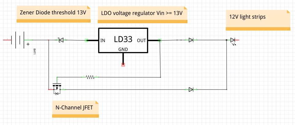
I looked at buck boost converters and couldn't find anything that looked helpful, and I didn't want to waste the power in doing a boost then buck converter. Is this schematic feasible? Below 13V, the JFET just stays on and passes power to the LEDs. 13V or more, the zener diode allows power to the LDO, which then passes 12V or so to the N-Channel JFET gate, turning off the JFET.

EDIT: I see that my poor schematic software is causing a lot of confusion. Fritzring does not have the parts I was trying to render. I am NOT using an LD33, but rather a typical 12V out, 2Amp load LDO voltage regulator. Here's the datasheet for the KA278R12C: http://www.mouser.com/ds/2/308/KA278R12C-1120707.pdf. This is not for a vehicle, but rather some indoor lighting hooked up to a battery.

Schematic

\$\endgroup\$
7
  • 4
    \$\begingroup\$ Uhm, no, this schematic is pure nonsense. You cannot "design" a circuit if you don't understand electronics. examples: the 13 V zener diode will drop 13 V so you will always have 0 V at the input of the LDO. That JFET is not a JFET but a NMOS MOSFET, A JFET would be unsuitable for this. The output of the LDO will have a voltage that will always switch on the NMOS so the NMOS does nothing. Yep, circuit design isn't easy, took me several years to master it. \$\endgroup\$ Commented Oct 26, 2017 at 6:19
  • \$\begingroup\$ @Bimpelrekkie are you implying that one can ever master circuit design? All I' ve ever found is that whenever you think you know what you are doing someone points out a problem that makes you go "oh, damn, well, I guess I didn' t think of that..." \$\endgroup\$
    – Joren Vaes
    Commented Oct 26, 2017 at 6:39
  • \$\begingroup\$ @JorenVaes "oh, damn, well, I guess I didn' t think of that..." Well that happens less and less to me so I might be getting there. I've been looking at and making circuits for almost 30 years now. It also helps that as I get older I have simply seen more things than others do so simply staying at it (circuit design) helps as you get more experience by the years. \$\endgroup\$ Commented Oct 26, 2017 at 6:47
  • \$\begingroup\$ The actual solution to OP's problem can be quite easy. Unfortunately OP does not mention one very important parameter value which prevents me from suggesting a practical design. Who can guess what parameter I need? \$\endgroup\$ Commented Oct 26, 2017 at 6:52
  • \$\begingroup\$ @vik Add a link to the datasheet of your LDO. Most simple LDO's I know will not stop working below 13V. This voltage is given as the minimum at which the output will be 12V. If your input falls below 12V+minimum required margin, the output will be lower than 12V. Thats all. This means that all diodes , zeners, MOSFETs in your circuit are not necesсary. Just connect your LDO like the default implementation circuit given in the datasheet. It will provide no more than 12V. \$\endgroup\$ Commented Oct 26, 2017 at 6:53

2 Answers 2

2
\$\begingroup\$

The LD33 is a code for an SMT fixed 3.3V version of the LM1117, which is a semi-LDO regulator. It won't be of any help.

If you set up an appropriate LDO regulator with 12V out it alone will do what you want. Above 12V plus a bit it will provide 12V out (and will be called upon to dissipate a lot of power perhaps), and below 12V plus the dropout voltage (down to a few volts) it will provide the input voltage less a small drop, typically.


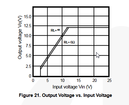
Edit: Given a potential part number, the above paragraph can be illustrated with a figure from the datasheet:

enter image description here

As you can see the output voltage tracks the input voltage (above a few volts) with a small voltage drop of some hundred of mV that depends a bit on the loading.. until it gets to a bit over 12V at which time the regulator begins to regulate and limits the output voltage to 12V nominally.

/Edit


There are many potential pitfalls in what you are trying to do- aside from current and heat, the situation you describe implies a vehicle electrical system which has a whole associated set of concerns. Also keep in mind that a 12V battery doesn't stay at 12V- it drops as the battery is discharged- significantly. Your LED lights will probably get dim from a relatively small drop in voltage. Also, its normal to consider some kind of low voltage cutoff so the battery is not damaged by accidentally running it flat.

\$\endgroup\$
2
  • \$\begingroup\$ I apologize for the confusion. The LD33 is not what I am using (bad software), but rather KA278R12C or similar. What potential pitfalls are you seeing? \$\endgroup\$
    – vik
    Commented Oct 26, 2017 at 15:06
  • \$\begingroup\$ Transients on the vehicle (if it is) electrical system. Suitable heat sinking. Maximum current. That part looks potentially suitable if protected from transients as may be necessary. See if you understand figure 21, it basically tells you what I said in the 2nd paragraph above. \$\endgroup\$ Commented Oct 26, 2017 at 18:22
0
\$\begingroup\$

Assumed specs , since incomplete given: Vbat=11.5~14.2V LED(4S)=11.6~12.4(est)nom.@ ??? mA, therefore dim at low Vbat.

If limited range and 0.1V LDO with CC current sense, or R current limiter. Is better choice.

OK using low RdsOn FET and Vref with comparator.

Ideal is buck/boost SMPS CC regulator designed to match both input and output V/mA~A specs

\$\endgroup\$

Your Answer

By clicking “Post Your Answer”, you agree to our terms of service and acknowledge you have read our privacy policy.

Not the answer you're looking for? Browse other questions tagged or ask your own question.