0
\$\begingroup\$

Today I "played" with a relay for the first time.

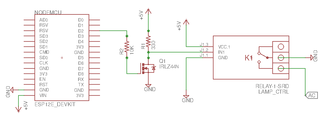
I only had an N-channel MOSFET available (an IRLZ44N) and wanted to control the relay from an ESP8266's GPIO pin - i.e. use a 3.3V signal to control the relay's input pin, which expects 0 or 5V.

ESP8266 controlling a 5V relay with an N-channel MOSFET

  • I had a 10K resistor handy, so I used it to current-limit the fet's Gate. To my understanding, MOSFETs only care about voltage, not current - so a "big" current limiter at the gate shouldn't matter anyway.

  • When the IRLZ44N is off, the relay's input is connected to the 5V over R1 - and when it's on, the input goes to ground. At that operational mode a resistor is needed; without it, the 5V would end up going directly to ground.

The circuit works - I tested it and the relay responds as expected. But measuring voltages, I saw that the voltage after R1 is not 5V; it's less, since some current goes in the relay's input. In doing so, the voltage drops from 5V to 3.5V; there's approximately 5mA going in the relay's input, and 1.5V ends up being wasted on R1.

It seems that if I had used a larger R1, the circuit wouldn't work - the voltage would drop too far. And as-is, 3.5V may be a marginal situation for the relay. EDIT: Using the 3.3V signal from the ESP directly on the IN1 input doesn't trigger the relay - so it seems the 3.5V we reach with this circuit is indeed borderline

Another disappointing thing about this circuit: when the relay is off, we waste current through R1.

Can you guys recommend a better circuit to use with my IRLZ44N, to turn the ESP8266's 3.3V to 5V and optimally control my relay?

Thanks in advance.

\$\endgroup\$
11
  • \$\begingroup\$ Hmm, mechanical relays have coils, not "In, Gnd, Vcc". Do you have an actual relay or is it a module? And while ideal FETs gates don't care about current, real FETs do have a parasitic capacitor, so a lower resistor would be better (not that much of a problem here though). \$\endgroup\$
    – Wesley Lee
    Commented Nov 5, 2017 at 15:59
  • \$\begingroup\$ It's this relay: tkkrlab.nl/wiki/Arduino_KY-019_5V_relay_module - indeed, it's a module. \$\endgroup\$
    – ttsiodras
    Commented Nov 5, 2017 at 16:23
  • \$\begingroup\$ It is likely your N-FET circuit is unnecessary and somewhat unhelpful, however your link does not provide any credible documentation of the relay's internal circuit, so it's not possible to make any definitive statements. The PCB seems simple enough that you might be able to reverse engineer it by the combination of visual inspection and some ohm meter measurements when unconnected to anything. \$\endgroup\$ Commented Nov 5, 2017 at 16:43
  • \$\begingroup\$ @ChrisStratton My first attempt was obviously using the 3.3V signal as-is into the IN1 pin of the module - but the relay didn't fire, so the "unnecessary" part is at least debatable :-) Regardless, assuming that we indeed need 5V and that the only accessible FET is this N-channel one... any idea on a better circuit to raise the 3.3 to 5? \$\endgroup\$
    – ttsiodras
    Commented Nov 5, 2017 at 17:32
  • \$\begingroup\$ Found a "schematic" for the module on this website. Its likely incorrect as S8550 is a PNP part, they probably meant S8050. \$\endgroup\$
    – Wesley Lee
    Commented Nov 5, 2017 at 17:40

2 Answers 2

1
\$\begingroup\$

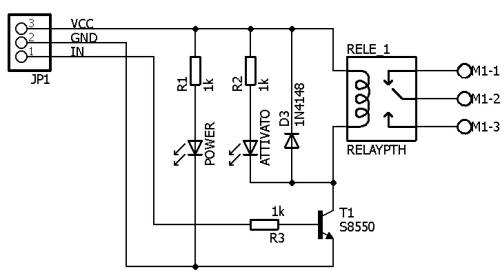
I found the following schematic on this website. Its likely incorrect in some parts though, as S8550 is a PNP part, they probably meant S8050.

enter image description here

Since you stated that directly plugging a 3.3V signal didn't work, you can try one of the following (considering your N-FET limitation):

  • Use your IRLZ44 to directly drive the relay
  • Put a resistor in parallel with R3, to increase the current going into the NPNs base and try to trigger it with 3.3V again.

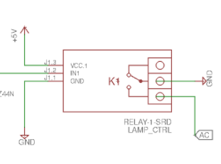
p.s.: I hope you aren't actually connecting GND to AC with your relay as it could be quite unpleasant/dangerous:

enter image description here

\$\endgroup\$
10
  • \$\begingroup\$ About the p.s: :-) About the rest, if that was the schematic of my relay module, I don't see why the 3.3V of the ESP wouldn't work as-is; the BJT would conduct, no? But TBH, I am still hoping for a solution that doesn't involve opening the relay module - i.e. a circuit that gives a "better" 5V than my puny 3.5V (using the N-FET). \$\endgroup\$
    – ttsiodras
    Commented Nov 5, 2017 at 17:59
  • \$\begingroup\$ Well, you could use a smaller R3, but it will draw more power when you want the relay to be off. I also thought it was strange that 3.3V wasn't enough to switch the transistor on.. but maaybe the base resistor is higher than 1k or, the transistor has low Hfe. Might be worth the try just adding a resistor in parallel. \$\endgroup\$
    – Wesley Lee
    Commented Nov 5, 2017 at 18:05
  • \$\begingroup\$ The 3.3v signal input is probably fine, but the relay may need to be supplied something closer to 5v. However, either your original measurement of 5 mA is wrong, or this is not the circuit and component values of your relay module. \$\endgroup\$ Commented Nov 5, 2017 at 18:05
  • 1
    \$\begingroup\$ @ttsiodras - people are ignoring the 3.3v to 5v via an NFET as an N channel device is the wrong part for sourcing current from a higher voltage, and because level translation is tangential to an efficient solution to your problem. \$\endgroup\$ Commented Nov 5, 2017 at 18:12
  • 1
    \$\begingroup\$ There are other level shifters with N-FETs other than the one you used such as this one, but they will have the same problem as R3 since they also depend on pull-ups. Other options would be more complicated than just directly driving the relay with your IRLZ44. (Maybe a high side N-FET? Then you would need some sort of drive voltage way higher than 3.3V for the gate..) \$\endgroup\$
    – Wesley Lee
    Commented Nov 5, 2017 at 18:22
0
\$\begingroup\$

There are 3V relays and relay modules are available.

I have had similar a problem and tested a BT136 on 10W LED bulb and it worked.

BT136 only only needs 10mA at 2V but is a health-hazard if no optocoupler are used.

\ref ESP MCU, directly drive BT136

\$\endgroup\$
0

Your Answer

By clicking “Post Your Answer”, you agree to our terms of service and acknowledge you have read our privacy policy.

Not the answer you're looking for? Browse other questions tagged or ask your own question.