0
\$\begingroup\$

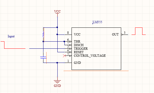
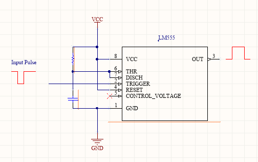
I'm using a lm555 IC in monostable mode. When my input varies from 5v to 0v the output goes from 0v to 5v. But this only happens perfectly if it happens just a pulse at the entrance, in case my input changes from 5v to 0v and continue at 0v for the rest of the time the output does not work correctly. What I want is the following, when my input changes from 5v to 0v and continue to 0v, I want my output to remain high only for the time I have determined.

What I have:

enter image description here

What I need:

enter image description here

I thought I could do that with transistor input, but I did not find a way to do it. If anyone knows something similar thank you.

\$\endgroup\$
4
  • \$\begingroup\$ I'd use an edge detector on the trigger input to ensure that the trigger pin of the 555 only sees a short pulse rather than the steady-state 0V signal \$\endgroup\$
    – DerStrom8
    Commented Nov 6, 2017 at 12:52
  • \$\begingroup\$ My input (pin2) gets 5v or 0v, never just a pulse. Always a continuous signal, 0v or 5v. \$\endgroup\$ Commented Nov 6, 2017 at 12:57
  • \$\begingroup\$ I don't think you read my comment. I said to use an edge detector to give you the short pulse. The edge detector will generate a short pulse when it sees a transition from 5V to 0V. You would use that short pulse to trigger your 555 \$\endgroup\$
    – DerStrom8
    Commented Nov 6, 2017 at 13:05
  • \$\begingroup\$ Thank you, my doubt was the same as the following post:electronics.stackexchange.com/questions/311822/… I made the changes and it worked. \$\endgroup\$ Commented Nov 6, 2017 at 16:12

1 Answer 1

3
\$\begingroup\$

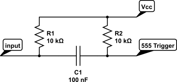
If you add the following components onto the trigger input you will create the required trigger pulse for every negative edge. you may need to adjust the component values to suit your application.

schematic

simulate this circuit – Schematic created using CircuitLab

\$\endgroup\$

Not the answer you're looking for? Browse other questions tagged or ask your own question.