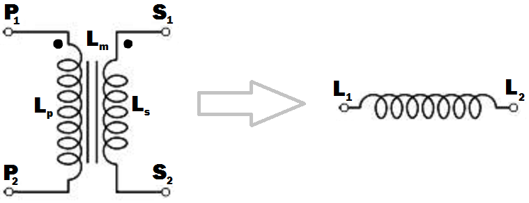
Just use the primary or the secondary with the other winding open-circuit. If you use the primary, the inductance will be \$L_P\$, and if you use the secondary it will be \$L_S\$ - by definition.
But I'm not sure what you are expecting to do with this (you say you don't want to use any other circuit elements .... ?).
The frequency response will depend on what other circuit elements you use. Assuming you are trying to implement an L/R or L/C low-pass filter, a mains transformer should give rejection up to a few tens of kHz before other factors (such as winding capacitance) have an effect.
Be aware though that the primary of a mains transformer will have higher inductance and will be rated for higher voltage and lower current than the secondary. You should also ensure that if you do not use one winding is well insulated, especially if you are using the secondary. This is because very high voltages could be induced in the primary if the secondary current changes rapidly.
EDIT
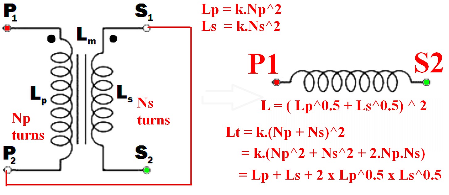
I see from your edits that you want to connect the windings together. The primary and secondary inductances can be calculated from their turns by the formulae ..
SECOND EDIT
I have rewritten this next part to make it less mathematical, more intuitive, and to distinguish it from other answers here.
The voltage induced across an inductor is proprrtional to the rate of change of current through it, and the constant of proportionality is the inductance L.
V1 = L * (rate of change of current through winding)
With coupled coils, the induced voltage has an extra factor due to the rate of change of current through the other winding, the constant being the mutual inductance Lm.
V2 = Lm * (rate of change of current through the other winding)
So in general, the voltage across the inductor is the sum of these:- (using your symbols)
Vp = Lp * (rate of change of primary current) + M * (rate of change of secondary current)
and for the secondary :-
Vs = Ls * (rate of change of secondary current) + M * (rate of change of primary current)
If we wire the primary and secondary in series, the currents are the same and the voltages will add or subtract,
depending on which way round we connect the windings together.
\$V_{total} = V_P \pm V_S = ( L_P \pm L_M + L_S \pm L_M )\$ * (rate of change of current)
SUMMARY
But this is just the same as if we had an inductor with inductance :-
\$L_t = L_p + L_s \pm 2L_m\$
If we connect the windings so that S1 is connected to P2, the current will flow the same way through both windings, the voltages will add and we maximize the inductance, so :-
\$L_t = L_p + L_s + 2L_m\$
If there is no coupling (for instance if the windings were on separate cores), the mutual inductance will be zero and the primary and secondary inductances will add as you might expect. If the coupling is less than perfect, a proportion k of the flux from one winding will couple into the other winding, with k varying from 0 to 1 as the coupling improves. The mutual inductance can then be expressed as :-
\$L_m = k\sqrt{L_pL_s}\$
and
\$L_t = L_p + L_s + 2k\sqrt{L_pL_s}\$
This is the same as Russell's answer if k=1 (perfect coupling) but I disagree that the mutual inductance is not relevant. It is.


