I'm on a (very) long and arduous journey to build a RF sweep generator for tuned circuit filters. After much experimentation with free running LC oscillators, I conclude that for this application (and keeping things analogue), some form of AGC to control the amplitude is key. This is the context that finds me reviewing circuit diagrams for the venerable Wavetek 1067 and I'm quite perplexed by what I find there.
Wavetek 1067 User Manual - Circuit diagram on pg.73
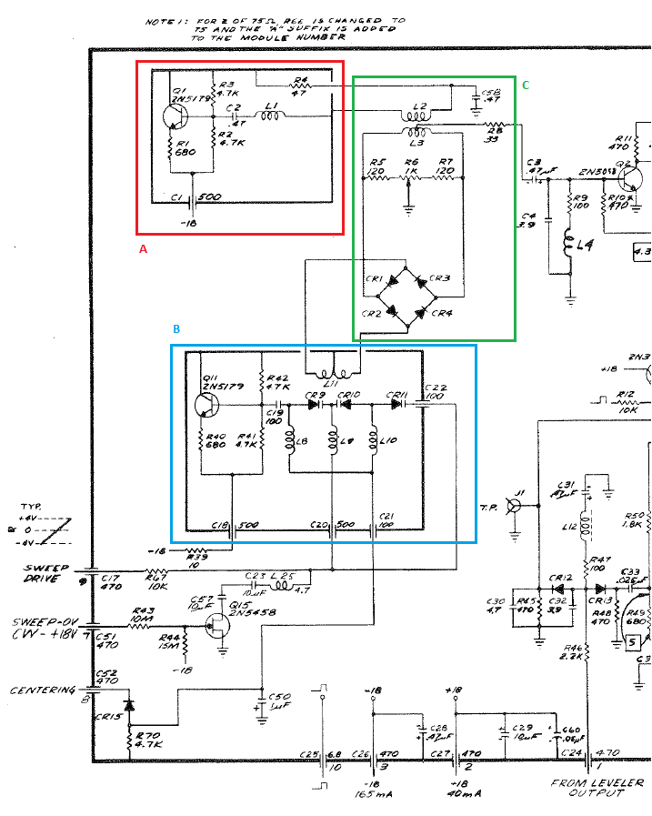
Here's an annotated snippet from the main sweep oscillator board:
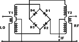
I'm guessing that section B (Blue box) is the main sweep oscillator with L8 - L10 and varactors CR9 - CR11 forming the main tuning components. L11 isn't coupled to anything (that I can see) and so forms a tapped inductor, where the centre tap is at the potential of either CR1/CR2 or CR3/CR4 (it isn't a fullwave bridge although it's drawn that way!)
So, it seems that CR1 to CR4 form a kind of amplitude limiting circuit (2 diode drops) whose DC bias is controlled by R6. The signal is then coupled to L2 and here's where is falls off the cliff for me. What exactly is the purpose of section A? I can see that the signal exits through the centre tap of L3 to the rest of the circuit - but section A doesn't seem to go anywhere??
My guess (for what it's worth) is that the amplitude limiting circuit in section C produces a lot of harmonic content (I know this because I've tried this kind of clipping myself and the resulting sine wave is nasty) and section A is there to improve the wave shape. But that's a wild guess.


