0
\$\begingroup\$

I am looking at using two p-ch MOSFETs in series as part of a high-side load switching scheme, and do not understand the following circuit behaviour.

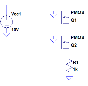
In simulation of the simplified schematic below, no current is driven into the load:

enter image description here

Edit: The MOSFETs being modelled are DMP2008UFG, model supplied by manufacturer

If neither Q1 or Q2 are conducting, Q2 has a floating source voltage and therefore undefined Vgs.

What I expected to happen:

  • Q1 to turn on, as its Vgs > Vth.
  • As Q1 is on, then Q2's source if no longer floating and is instead defined at near Vcc.
  • As Q2's Vgs>Vcc, Q2 conducts
  • Current flows into the load

Clearly I am misunderstanding the circuit. Why does no current flow into the load?

Many thanks in advance,

Gerry

\$\endgroup\$
6
  • \$\begingroup\$ If neither Q1 or Q2 are conducting, Q2 has a floating source voltage and therefore undefined Vgs. OK, so you don't know what Vgs of Q2 is. Does it matter? Imagine what happens if Vgs of Q2 were large and if it was small. Would that make any difference to the current through the load? \$\endgroup\$ Commented Nov 23, 2017 at 12:35
  • \$\begingroup\$ I ran a simulation on ISIS with two 2SJ118 P-Ch. MOSFETs and other elements same as shown in the question. 9.99mA flows through 1k resistor. NOTE: ISIS uses Spice. \$\endgroup\$ Commented Nov 23, 2017 at 12:37
  • \$\begingroup\$ I might be wrong but it looks like those MOSFETs are undefined and if so it won't work. I don't have any SPICE on hand to test this though. \$\endgroup\$
    – jaskij
    Commented Nov 23, 2017 at 12:49
  • \$\begingroup\$ FETs with trivial models may work different to real ones. Try a large (10M+ resistor from the floating node to ground. If the model has no capacitances and the input is "just there" and capacitive effects are missing. In real world ccts of this general sort very large leakage and bias currents and capacitive coupling as wavefprms or DC are applied can cause switching of parts which may stay off in "ideal" situations. \$\endgroup\$
    – Russell McMahon
    Commented Nov 23, 2017 at 13:18
  • \$\begingroup\$ Bimpelrekkie- no, I didn't think that it should matter, but I just thought it important to outline my thinking as I wasn't seeing the expected outcome. \$\endgroup\$
    – Gerry
    Commented Nov 23, 2017 at 13:53

2 Answers 2

1
\$\begingroup\$

Without more information, it's hard to say, but I suggest that you may be using ideal FETs in your simulation. Ideal FETs will have no leakage current, so the junction between the two will be floating, so the top FET, even though turned on, draws no current and its model doesn't work well.

I suggest two possibilities. The first is the most obvious - replace the FETs with actual, real part numbers. These will have leakage currents modeled which will allow more realistic operation.

The second is like unto the first. Place a fairly high resistance, say 1 to 10 megohms, between drain and source of each FET.

\$\endgroup\$
2
  • \$\begingroup\$ Parallel thinkings :-) \$\endgroup\$
    – Russell McMahon
    Commented Nov 23, 2017 at 13:21
  • \$\begingroup\$ It is indeed a feature of the simulation. I had been using two DMP2008UFG fets (model as supplied by manufacturer). Switching these to A06407's produced the expected behaviour. Thanks for your help. \$\endgroup\$
    – Gerry
    Commented Nov 23, 2017 at 13:45
1
\$\begingroup\$

FETs with trivial models may work different to real ones.
Spurious, leakage and informal coupling can lead to enough drive to "get things going".

Try a large (10 M+) resistor from the floating node to ground or supply.

If the model has no capacitances and the input is "just there" capacitive effects that may make a difference in the 'real' world are missing.
In real world circuits of this general sort, very small leakage and bias currents and trace capacitive coupling as waveforms change or as DC is applied can cause switching of parts which may stay off in "ideal" situations.

\$\endgroup\$
1
  • \$\begingroup\$ Gotcha! Ninja'd! \$\endgroup\$ Commented Nov 23, 2017 at 13:23

Your Answer

By clicking “Post Your Answer”, you agree to our terms of service and acknowledge you have read our privacy policy.

Not the answer you're looking for? Browse other questions tagged or ask your own question.