0
\$\begingroup\$

There are several ways to bias the quiescent point of transistor, when used as an amplifier. Among which voltage divider is best known for its improvements (improved temperature drift and beta variation). But as we use different transistors, even voltage divider cannot make amplifier beta independent.

enter image description here

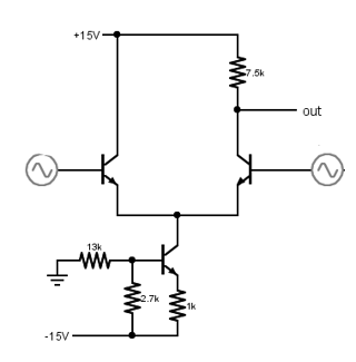
I am specially interested in the biasing of differential transistor pair (amplifier), where biasing is done only by replacing emitter resistor with active device known as constant current source, or should be done; as stated in Wikipedia and many other sites:

...the differential pair is directly biased from the side of the emitters by sinking/injecting the total quiescent current. The series negative feedback (the emitter degeneration) makes the transistors act as voltage stabilizers; it forces them to adjust their VBE voltages (base currents) to pass the quiescent current through their collector-emitter junctions...

I somehow still don't understand how a transistor could conduct any current without Vbe connected between the base and emitter of transistor. But by forcing the Vbe to "occur" and conduct current, whereas Vbe is forced by the current source...

What is actually happening here? Or can you at least show a practical example, where this kind of biasing is put into use?

\$\endgroup\$
14
  • \$\begingroup\$ You can read some articles from Bob Cordell: Designing Audio Power Amplifiers. The degeneration resistors are put in series with emitters even with current source as depicted. \$\endgroup\$ Commented Nov 26, 2017 at 21:36
  • \$\begingroup\$ Saying it forces Vbe is not a good explanation. Having the current source connected to the emitter produces whatever emitter voltage is needed to allow that current through. For example if the voltage at the base is 0V, the emitter will be at -0.6v, if 5V, then 4.4V, etc. \$\endgroup\$
    – τεκ
    Commented Nov 26, 2017 at 21:37
  • \$\begingroup\$ @τεκ If the constant current source is placed instead of emitter (tail) resistor: If there is no voltage across the base-emitter diode of diff. pair then no current flows through it and the constant current source collector sees the diff pair as huge resistor (as none of them conducts), and therefore no current should be flowing through both. That is how I see it... \$\endgroup\$
    – lucenzo97
    Commented Nov 27, 2017 at 9:40
  • \$\begingroup\$ Any diff. pair amplifier needs a DC current path for the base current. Is this so hard to understand? \$\endgroup\$
    – G36
    Commented Nov 27, 2017 at 13:45
  • \$\begingroup\$ @G36 As wikipedia says (if I understood correctly), there should be no voltage divider but only current source at emitter to bias the base of transistor.. \$\endgroup\$
    – lucenzo97
    Commented Nov 27, 2017 at 13:48

3 Answers 3

2
\$\begingroup\$

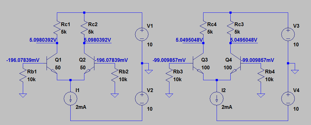
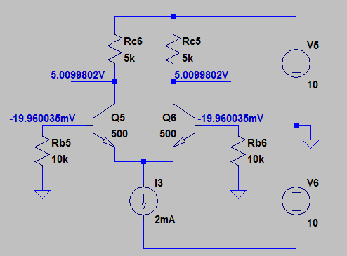
Look at the example when you can see that indeed the \$I_{C1}\$ and \$I_{C2}\$ are almost beta independent. There is a slightly \$\beta\$ influence because \$Ic = I_E\cdot \frac{\beta}{\beta + 1}\$

enter image description here

enter image description here

In this circuits we have:

$$I_{C1} = I_{C2} = 0.5\cdot I_{EE}\cdot\frac{\beta}{\beta + 1} $$

And the base current is:

$$I_B = \frac{I_C}{\beta}$$

The voltage at the base is:

$$V_B = -I_B\cdot R_B$$

\$\endgroup\$
1
\$\begingroup\$

enter image description here

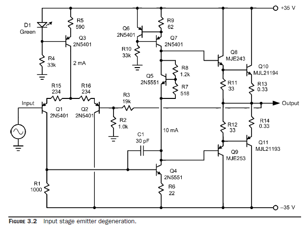
Source: Bob Cordell, Designing Audio Power Amplifiers

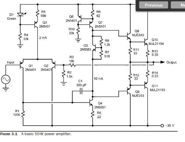
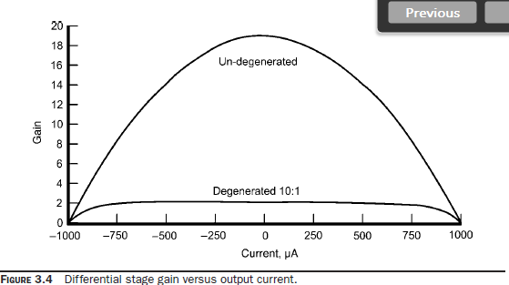
The design of Figure 3.2 differs from that of Figure 3.1 by the addition of emitter degeneration resistors R15 and R16 and by reducing C1 from 300 pF to 30 pF. The pair of 234-Ω emitter degeneration resistors implements 10:1 degeneration of the input differential pair by increasing the total emitter-to-emitter resistance RLTP from 52 Ω to 520 Ω. This reduces its transconductance by a factor of 10. In order to keep the negative feedback gain crossover frequency fc at the same 500 kHz for equivalent stability, C1 must be reduced by that same 10:1 factor.

enter image description here

enter image description here

\$\endgroup\$
2
  • \$\begingroup\$ Ok, I get the degeneration thing but why isn't the base of Q1 biased to set Q point of operation? If it is not set then the crossover distortion occurs and amplifier wouldn't work properly. \$\endgroup\$
    – lucenzo97
    Commented Nov 27, 2017 at 13:57
  • \$\begingroup\$ If you disconnect the Q1 base or remove the input signal source. Q1 will be cut-off and Q2 will be fully ON. Hence Q4 is OFF. And Q7 will be in saturation and the output voltage will reach positive saturation voltage Vout_max = Vcc - 0.2V - 2Vbe. No crossover distortion will occur. \$\endgroup\$
    – G36
    Commented Nov 27, 2017 at 14:15
1
\$\begingroup\$

@Keno - the basic principle of the simple diff. amplifier as shown in the first diagram (your question) is as follows:

  • There are two supply voltages (plus and minus) - and the whole circuit is balanced so that the dc voltage at the base nodes must be zero! This is desired because no voltage divider is required for biasing (high input resistance). The DC base current can/must be provided by the signal source - or we can use a simple resistor to ground (signal ac coupling with a capacitor) .

  • In this case, the DC potential at the common emitter node must be app. Ve= 0.65...0.7 volts. Then, both npn-transistors have the necessary voltage Vbe for proper operation. Of course, there are base bias currents in to the base nodes - however, these currents can be regarded as (unwanted) secondary effects. Remember - the BJT is a voltage-driven device Ic=f(Vbe).

  • The active circuit in the common emitter path (current source Io) is able to automatically adjust the emitter potential to the value Ve required by the wanted currents Ic1=Ic2=Io/2.

  • This biasing method is always used in the diff. input stages for all operational amplifiers. Sepatae biasing is necessary only if unsymmetrice power supply is used.

  • As a consequence, the "beta variation" as mentioned by you (beta dependence, beta symmetry) is of less importance for proper operation of the whole circuit.

  • EDIT (added): Further explanation to the "automatic adjustment" mentioned above (3rd point):

For each opamp with voltage feedback an automatic adjustment takes place whch makes the input differential voltage negligible small (bcause of the huge open-loop opamp gain).

A similar effect occurs in the diff. amplifier under discussion. The network in the common emitter path (resistor or an active circuit acting as a very large dynamic resistor) also provides heavy voltage feedback - and the result is an automatic adjustment of the voltage between B and E - nevessary for proper operation with the designes collector currents.

\$\endgroup\$
5
  • \$\begingroup\$ Thank you for this contribution. How long did you have to scroll to find this? :D Anyway, yes, the biasing in such situation wasn't clear to me at that time. As long as you provide appropriate voltage difference to emitter junction of BJT, it doesn't really matter what kind of biasing you use, I guess. Even the resistor to GND isn't needed if source's offset is zero, meaning base of BJT is floating until you apply signal generator to it and after that, the base is tied to GND and therefore biased. \$\endgroup\$
    – lucenzo97
    Commented Mar 3, 2022 at 20:25
  • \$\begingroup\$ Beta dependence could be also proven through proper nodal analysis, I guess. \$\endgroup\$
    – lucenzo97
    Commented Mar 3, 2022 at 20:26
  • \$\begingroup\$ Keno - I really do not understand your remark regarding "to scroll". Regarding your last comment (beta dependence) you should realize that all gain expressions (common mode and diff. mode) contain only one BJT parameter: Transconductance gm with gm=d(Ic)/d(Vbe)=Ic/Vt . This parameter is nothing else than the slope of the voltage control function Ic=f(Vbe). \$\endgroup\$
    – LvW
    Commented Mar 4, 2022 at 8:05
  • \$\begingroup\$ "I really do not understand your remark regarding "to scroll"." Ah sorry then, I though you might have had trouble finding this question because it is pretty old. But it looks like it was easily noticeable since someone recently edited it :) \$\endgroup\$
    – lucenzo97
    Commented Mar 4, 2022 at 21:48
  • \$\begingroup\$ I must admit that only now I have realized that the original question is already 5 years old...funny. \$\endgroup\$
    – LvW
    Commented Mar 5, 2022 at 9:12

Your Answer

By clicking “Post Your Answer”, you agree to our terms of service and acknowledge you have read our privacy policy.

Not the answer you're looking for? Browse other questions tagged or ask your own question.