0
\$\begingroup\$

I'm trying to figure out a good LED + resitor pairing for my circuit. However, I'm provided with a challenge and limited knowledge.

Here's the situation: I'm creating a minimized version of THIS sensor board. The board breaks out THIS sensor, which requires a 3.3V supply voltage. To minimize the size, I took out all voltage regulating components. Now I need to power a white LED with 3.3V and add a current limiting resistor. Getting a sufficient voltage drop is the challenge for which I could use some help.

Now, my solution was to increase the supply voltage to 3.6V instead of 3.3V, which shouldn't be a problem for the color sensor according to the datasheet. I found THIS LED with a supposed forward voltage of 2.8V and current of 20mA. With this situation I CALCULATED that I would need a resistor of at least 47 ohm. Would my suggested solution work or did I miss something??

\$\endgroup\$
6
  • 1
    \$\begingroup\$ Just FYI, running the chip at or near the maximum voltage will probably reduce the sensor life. I'm confused about why you need to "get a sufficient voltage drop"? \$\endgroup\$
    – Ron Beyer
    Commented Nov 27, 2017 at 16:45
  • \$\begingroup\$ I'd stick with 3.3 and a 25R resistor. What's your variance on the 3.3V though. \$\endgroup\$
    – Trevor_G
    Commented Nov 27, 2017 at 16:52
  • \$\begingroup\$ @RonBeyer the sensor will be used in a research application, a short lifespan is expected. \$\endgroup\$
    – RMD
    Commented Dec 1, 2017 at 13:01
  • \$\begingroup\$ @Trevor It's hard to predict the variance on the 3.3V, which is why I hope increasing voltage to 3.6V would give me more wiggle room. And to get 3.6V I would need a regulator which hopefully provides more stability. \$\endgroup\$
    – RMD
    Commented Dec 1, 2017 at 13:04
  • \$\begingroup\$ I have solutions for you, but since it sound like you are already stuck for space... I hesitate to give them. \$\endgroup\$
    – Trevor_G
    Commented Dec 1, 2017 at 13:11

4 Answers 4

1
\$\begingroup\$

I found THIS LED with a supposed forward voltage of 2.8V and current of 20mA.

It's worse than you thought!

enter image description here

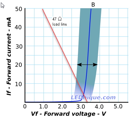
Figure 1. The ASMT-UWB1-Nxxxx datasheet LED could \$ V_f \$ could vary between 2.8 and 3.6 V at 20 mA.

enter image description here

Figure 2. The blue shaded region represents the possible values of I versus V for your LED. The 47 Ω load-line is superimposed on the chart. Data is for the LTST-C170TBKT but looks similar to OP's LED. Source: Variations in Vf and “binning”.

Depending on the actual value of \$ V_f \$ for your LED the current will be 12.5 mA at lowest \$ V_f \$ to about 1 mA at the highest.

enter image description here

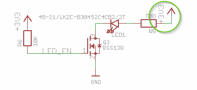
Figure 3. The LED is powered from 3.3 V.

The easiest solution is to disconnect R5 from the 3.3 V supply and power the LED from the unregulated voltage.

enter image description here

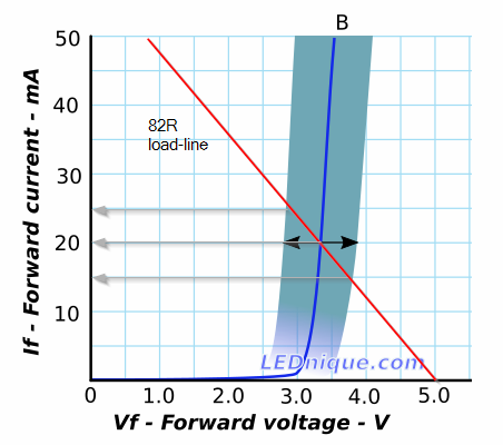
Figure 4. The load-line for an 82 Ω resistor on a 5 V supply.

With a 5 V supply and an 82 Ω resistor the current would be 20 mA for the mid-range \$ V_f \$ but could vary by up to 5 mA each way depending on production spread. This is the difficult world of electrical engineering.

If you can increase the supply voltage you can also increase the series resistor which will make it more like a constant current source. The load-line will be less steep and the resultant currents will vary less for a given range of \$ V_f \$.

\$\endgroup\$
1
  • \$\begingroup\$ Thanks a lot for this explanation! It made me get a better understanding of what I'm dealing with. \$\endgroup\$
    – RMD
    Commented Dec 1, 2017 at 12:52
1
\$\begingroup\$

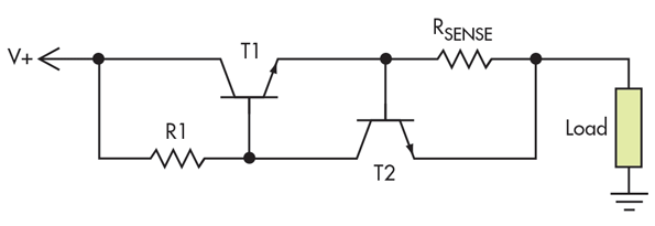
An alternative is to use a simple current limiter circuit instead of a series resistor. That will minimise the volt drop in cases where current is low. The following is about as simple as you'll get.

Current limiter circuit

Pick Rsense so that it produces about 0.6V at your max current. So for a 20mA LED, choose Rsense = 30Ω. When the current limit is hit, T2 will turn on, drawing the base current away from T1 and therefore inhibiting the current into the load.

\$\endgroup\$
4
  • \$\begingroup\$ what is R1 given OP's needs? \$\endgroup\$
    – dandavis
    Commented Nov 28, 2017 at 2:27
  • 1
    \$\begingroup\$ @dandavis about 1k seems to work well in simulation. It controls how aggressively T1 turns off. Probably best to start at 1k and tune from there. \$\endgroup\$ Commented Nov 29, 2017 at 10:47
  • \$\begingroup\$ Thanks for your feedback. Unfortunately I'm trying to minimize the size of my circuit board as much as possible. This doesn't give me any room for circuit additions like this. \$\endgroup\$
    – RMD
    Commented Dec 1, 2017 at 12:55
  • \$\begingroup\$ This circuit is fine if you have the extra volt and a bit available that it needs to operate. Going topside like that though, you are better using the PNP version or R1 has to be so small you end up powering the LED through T2. \$\endgroup\$
    – Trevor_G
    Commented Dec 1, 2017 at 14:01
0
\$\begingroup\$

The four options you have

  1. power the LED separately from a higher voltage.

  2. Use 3.6V with the original 3.3V led and a larger resistor.

  3. Use 3.3V with the original led and no/a smaller resistor and/or a lower current. You don't have to run it at the 20mA current and associated Vf.

  4. Use what you calculated, which is 100% fine.

You could use a constant current led tester set at 20mA to find out the actual forward voltage at Vf and adjust your led calculation based on that.

\$\endgroup\$
1
  • \$\begingroup\$ Option number 3 actually doesn't sound bad at all. I think it might be my best option so far. Thanks! \$\endgroup\$
    – RMD
    Commented Dec 1, 2017 at 13:43
0
\$\begingroup\$

If you have the room a simple solution is to add a small capacitive booster regulator.

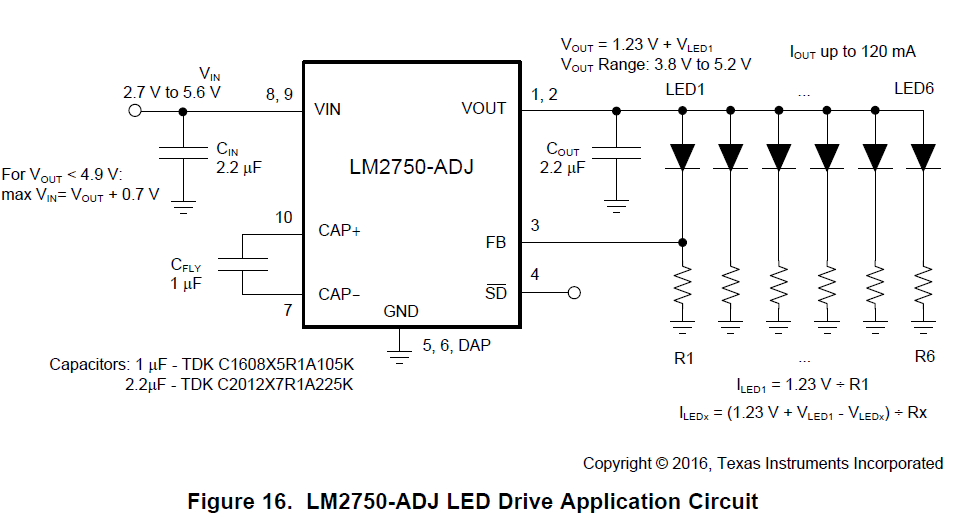
There are many available, but here is one, the LM2750-ADJ from T.I.

They have nicely given you the schematics to drive LEDS in the application examples. (I know you only need one LED, so ignore the extra five shown.)

enter image description here

Notice it regulates the current through the LED, you simply have to chose a value for R1 that sets up your If at 1.23V. It also has a simple logic level shutdown pin you can use to turn the LED on and off.

If you had to drive more than one LED, I'd suggest using one of the fixed output boosters to power all of them, and a traditional transistor/resistor switch for each individually.

\$\endgroup\$
2
  • \$\begingroup\$ Looking good! The sensor board is connected through a wire with a main board. Would increasing the distance between LED and capacitive booster regulator be problematic? If not, I would add the regulating circuitry on the main board while having the LED on the sensor board. \$\endgroup\$
    – RMD
    Commented Dec 1, 2017 at 13:40
  • \$\begingroup\$ @RMD, for a LED? hmm, I doubt the wire length would matter much. \$\endgroup\$
    – Trevor_G
    Commented Dec 1, 2017 at 13:57

Your Answer

By clicking “Post Your Answer”, you agree to our terms of service and acknowledge you have read our privacy policy.

Not the answer you're looking for? Browse other questions tagged or ask your own question.