7
\$\begingroup\$

How can I design a circuit which utilizes a photo-transistor to make a light sensitive switch that is when there is no light in room, the led connected to the photo-transistor lights up and when there is light in room, the led connected to Phototransistor turns off? Any schematic or circuit diagram would be really helpful.

Here is the link but I am using photo-transistor but this circuit is for LDR, so how can I use photo-transistor in this circuit?

enter image description here

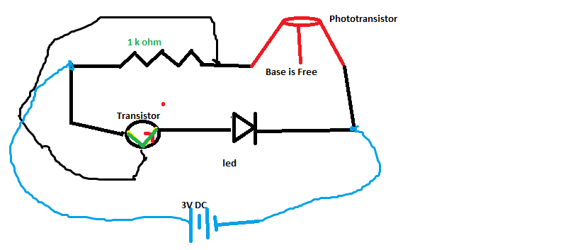
Here is my Implementation on breadboard. Please tell me if this is correct. I tried to make the two lines in parallel. I suspect my connectionof base of the transistor with resistor is wrong, correct me if I am wrong.SORRY I DID NOT HAVE ANY OTHER SOFTWARE TO SHOW MY IMPLEMENTATION SO PLEASE NEVER MIND :).

enter image description here

\$\endgroup\$
10
  • \$\begingroup\$ What did you already try and how didn't it work? What resources have you read (vedor app notes, etc.) and in what way weren't they clear? \$\endgroup\$
    – The Photon
    Commented Jun 21, 2012 at 15:44
  • \$\begingroup\$ PhotoTransistor has 3 legs,, emitter, base, collector, where as it has two and the resulting circuit picture doesn't have phototransistor, it has 2 leg led type sensor \$\endgroup\$ Commented Jun 21, 2012 at 16:04
  • 2
    \$\begingroup\$ @UmerFarooq, Phototransistors normally have 2 legs, Emitter and collector. Carriers are not injected through the base connection but instead from the light shining there. Is it possible that your phototransistor gives you a base connection to allow you to bias the transistor and then use the light to increase on top of a DC large signal Bias? I have used Phototransistors before with only 2 pins multiple times. \$\endgroup\$
    – Kortuk
    Commented Jun 21, 2012 at 16:07
  • \$\begingroup\$ so if I use 3 leg transistor, what should I do with the base leg.. \$\endgroup\$ Commented Jun 21, 2012 at 16:11
  • 1
    \$\begingroup\$ You can leave the base floating (unconnected) or connect it to ground through a resistor. You can bias the base to change the sensitivity to the light levels \$\endgroup\$
    – Oli Glaser
    Commented Jun 21, 2012 at 16:20

2 Answers 2

8
\$\begingroup\$

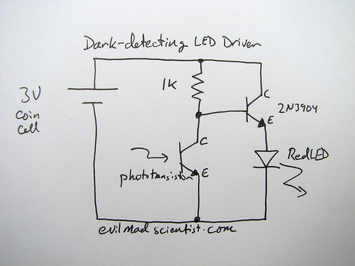
The circuit you show should work as it is, since it is already for a phototransistor. Just leave your base lead floating.

EDIT - the breadboard circuit you have added looks correct (though it's hard to read..) so go ahead and try it. If it doesn't work let us know. Maybe change the resistor to 2k or larger if you are worried about blowing the LED.

Just to note this circuit will work fine, although Steven's suggestion is "preferable" in general. I would maybe not change things till you have it working.
The reason the circuit is usually not the best way to do this is because it relies upon Hfe, which can vary quite widely in a transistor and is subject to temperature changes. This means the base resistor must be chosen according to the particular transistor used.

The reasons it is picked for this circuit are as it uses 1 less resistor (for size purposes, see picture below) Also this circuit is designed for a 3V cell like a CR2032, which has a high internal resistance and generally cannot supply enough current to damage the LED (so it's like having a series resistor in place) The original project page explains all this.
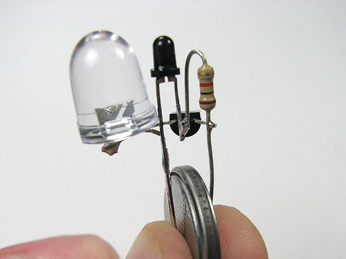
CR2032 light sensor

So if you are intending to eventually power this circuit from something else other than a coin cell, then you should go for the common emitter circuit Steven describes. The site you got the above circuit from also has an example of such a circuit:
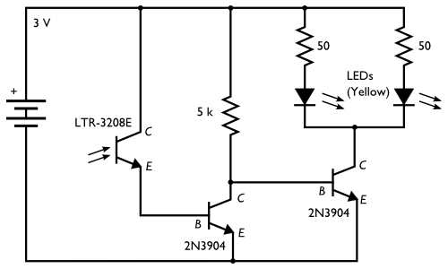
Common emitter light sensor

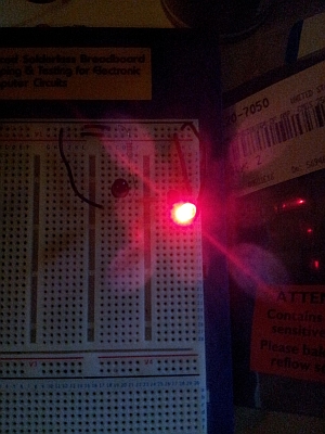
To help with the breadboard I just threw together the little circuit shown in your question. I only had an IR phototransistor but it doesn't matter much for this, it still works the same. Anyway here are a couple of pictures of it working, hopefully you can see how the connections go:
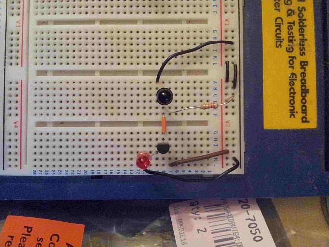
phototransistor light

The phototransistor base is floating, and I swapped the 1k for a 22k in my circuit to bias it correctly (I arrived at this value roughly, see below) and used a BC337 npn. Since the BC337 has lots of gain the 22k works well for the base current.
To give an idea of why the 22k resistor, the BC337 I'm using has a gain of around ~400, and the voltage it will see is 3V - (Vled + collector-emitter drop) -> 3V - (1.8V + 0.7V) = ~0.5V. So 0.5V / 22k = 23uA into the base.
The gain for the BC337-40 is typically 400, so 23uA * 400 = 9.2mA. The min/max gain given in the datasheet is 250-630, so the actual max LED current could vary from ~6mA to 14mA, which is within maximum LED current (20mA) My actual measured maximum current was 10mA, so this fits with the above calculations.
The power rails are on the right, red for +V and black for ground.

With the lights turned down a bit:
phototransistor dark

It actually works very well, off in normal light and starts turning on as soon as I start dimming the lights. You may have to try a few different values of resistor in your circuit to arrive at your desired setting.
\$\endgroup\$
13
  • \$\begingroup\$ Sir an error occured, The led lights up even when light is on. What do I do? \$\endgroup\$ Commented Jun 22, 2012 at 2:59
  • \$\begingroup\$ I am using 1K resistor \$\endgroup\$ Commented Jun 22, 2012 at 3:02
  • 1
    \$\begingroup\$ The 2N3904 has a lower gain than the BC337, so you don't really want to go higher than 20k as there won't be enough current to light the LED properly (there is likely something wrong with your phototransistor if it still doesn't work with above 10k - check it's correctly orientated) \$\endgroup\$
    – Oli Glaser
    Commented Jun 22, 2012 at 3:11
  • 1
    \$\begingroup\$ @Steven - I added a bit more, hopefully this makes things a bit clearer. Initially I was trying to keep things as simple as possible as it's clear the OP is very new to the subject (e.g. we still aren't quite sure whether he is using a phototransistor or LDR). I thought changing the circuit might just confuse things too much. \$\endgroup\$
    – Oli Glaser
    Commented Jun 22, 2012 at 10:43
  • 2
    \$\begingroup\$ @Steven - In general yes, but we'll have to agree to disagree on this one I think :-) For this particular circuit posted and with this particular OP (from previous questions) I thought keeping things as simple as possible was very important. Part of the learning can be finding out for himself why this circuit would be not ideal in most situations, and then trying it other ways. In any case he has plenty of info about both versions now :-) \$\endgroup\$
    – Oli Glaser
    Commented Jun 22, 2012 at 12:13
7
\$\begingroup\$

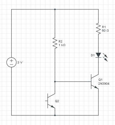
First move the LED to the transistor's collector, and add a series resistor. You now have a common collector circuit, and the 2N3904's base is at 2.7 V or higher, depending on the LED voltage. Then if there's no current through the phototransistor you have 300 \$\mu\$A base current (0.3 V / 1 kΩ). If the transistor has an \$H_{FE}\$ of 100 you'll have 30 mA LED current and that may be too much. But the main problem is that \$H_{FE}\$ may have a wide variation, and the upper limit is often not even specified. You have absolutely no feedback in the circuit so that 30 mA may as well be 150 mA, probably destroying the LED in a circuit with a higher power supply. You do need a resistor, and with the LED on the collector's side your series resistor will limit the current.

enter image description here

edited to explain it better This is the circuit you should get. If phototransistor Q2 does not draw current, then Q1's base gets current through R2. The base is at 0.7 V (always 0.7 V higher than the emitter), and the power supply is 3 V, so there's 3 V - 0.7 V = 2.3 V across R2. Then because of Ohm's Law the current through R2 = 2.3 V / 1 kΩ = 2.3 mA. Transistor Q1 will want to increase that 100-fold to get 230 mA collector current. R1 will limit that. If Q1 is on then the LED's cathode will be at around 0 V, and the anode 2 V higher, at 2 V (that's typical for a red LED). So there remains 1 V for resistor R1, and if we want 20 mA through it (and the LED) we apply Ohm's Law again: R = 1 V / 20 mA = 50 Ω. So R1 will make sure that the LED current won't go higher than 20 mA.

Now if Q2 (the phototransistor) gets light it will also draw current, and draw it away from Q1. The more light, the more Q2 current, and the less Q1 base current. So that the LED will go dimmer with more ambient light.

\$\endgroup\$
2
  • 2
    \$\begingroup\$ Sorry Stevenvh never mind. Can you please show a picture or something, I am a newbie and can't really understand your explaination. No offence. \$\endgroup\$ Commented Jun 21, 2012 at 16:52
  • 1
    \$\begingroup\$ @Umer - I added a schematic and edited the text. If you don't understand it right away, read it a second time, and try to imagine the current flows. If yo still don't understand you can ask again, but then I expect that your question is specific about one part of the schematic. \$\endgroup\$
    – stevenvh
    Commented Jun 21, 2012 at 17:12

Your Answer

By clicking “Post Your Answer”, you agree to our terms of service and acknowledge you have read our privacy policy.

Not the answer you're looking for? Browse other questions tagged or ask your own question.