1
\$\begingroup\$

The project I am working on specifies a 12v 0 12v centre tapped transformer. I have a 12v twin secondary left over from a previous project. My plan is to wire the two secondaries in series in order to form a centre tap, as per this thread:

A question about using a dual secondary transformer as a center tapped transformer

My question is, I think this will double the voltage to 24v - is that correct? The project specifies 12v, so would I be better using a 6v twin secondary transformer with the secondaries wired in series?

I am a wee bit confused since a similar question was asked here:

https://www.eevblog.com/forum/beginners/replacing-centre-tap-transformer-with-standard-transformer/msg21738/#msg21738

The advice given was, "If you can't find a 12V centre tapped transformer, use a 12V transformer with twin secondaries and connect them in series"

I would be very grateful if someone could clarify.

Many thanks

\$\endgroup\$

1 Answer 1

6
\$\begingroup\$

The project I am working on specifies a 12v 0 12v centre tapped transformer.

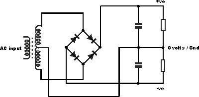
So most likely your project will use it to make split supplies (positive and negative) like this:

enter image description here

Your twin secondary transformer can perform the same role, simply connect the secondaries in series, and their connection becomes the center tap. Make sure you connect them the right way around!

Center tapped would be 12-0-12 and yours would be 12-0 and 0-12 !

Twin secondaries are more flexible because you can also put them in parallel to double the current, if you only need one 12V winding.

\$\endgroup\$
5
  • 1
    \$\begingroup\$ That is massively helpful - I'm glad to hear I can recycle my existing transformer! Many thanks! \$\endgroup\$ Commented Dec 4, 2017 at 11:06
  • \$\begingroup\$ Last question relating to this - after connecting the two secondaries in series, how do I then determine which of the two remaining terminals is +12v, and which is -12v. Many thanks again. \$\endgroup\$ Commented Dec 4, 2017 at 11:33
  • \$\begingroup\$ They're AC, so what decides the positive or negative polarity is the rectifier bridge. What is important is that, with "0V" being the center tap, both windings give opposite AC voltagesrelative to 0Vo the diode bridge does full wave rectification. You can check with a scope, but also with a multimeter. You should have 24V AC between the two 12 terminals if wired correct, and 0V if one is wired wrong in this case both windings voltage will cancel and it would not work... \$\endgroup\$
    – bobflux
    Commented Dec 4, 2017 at 12:46
  • \$\begingroup\$ Thanks again Peufeu - I can see now from the circuit diagram for the PSU I building will dictate polarity - many thanks again. Todays lesson learnt! \$\endgroup\$ Commented Dec 4, 2017 at 15:03
  • \$\begingroup\$ You're welcome, have a nice day! \$\endgroup\$
    – bobflux
    Commented Dec 4, 2017 at 16:30

Your Answer

By clicking “Post Your Answer”, you agree to our terms of service and acknowledge you have read our privacy policy.

Not the answer you're looking for? Browse other questions tagged or ask your own question.