0
\$\begingroup\$

I have a microcontroller TM4C123GXL Launchpad, that has 8 serial UART ports. I am using Keil uVision5 with Tiva Ware for programming.

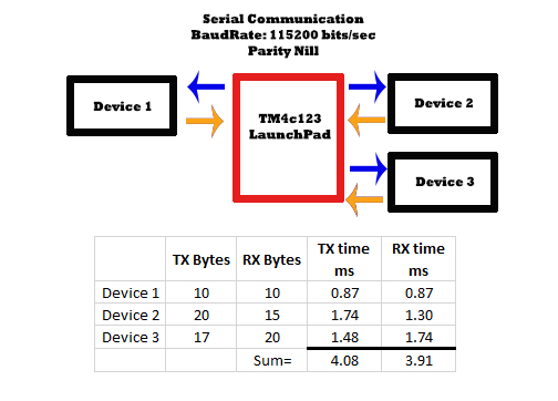
I wanted to interface 3 UART devices with the microcontroller without any loss of bytes. The baud rate has been set to 115200 bits/sec with no parity as shown in the figure below. All devices sent data frame periodically every 5ms.

Communication system

TX and RX time are calculated using No_0f_bytes*10/BaudRate

I have successfully interfaced the devices with the UART of µC. The problem in the communication is that that I am losing the bytes. If I do a communication with a single device (Device 2) I am still losing the bytes from the whole frame (20 bytes).

Is it due to the 16 byte FIFO limitation of Tm4c123 or anything else?

I have also implemented the µDMA feature of TM4C123. But still, bytes are lost. What can I do to improve the system for lossless transmission and reception of data frames?

Edit:

Here is the Software Architecture:

I am using Periodic Timer Interrupt of 5ms to receive and transmit the frame. All frame has first 2 bytes header and a counter byte as the last byte.

void Timer1IntHandler(void) //  Periodic Service Routine every 5ms
{

DisableIntrupts();

bool Correct=ReadJoystick(); //10 bytes  Device 1

if(Correct)
{
GenerateServoCardsFrame();

SendServo1Frame();   //20 bytes  Device 2
SendServo2Frame(); //17 bytes  Device 3
ReadServo1Frame();  //15 bytes Device 2
ReadServo2Frame();  //20 bytes Device 3

GenerateJoystickFrame();

SendJoystickFrame(); //10 bytes   Device 1

EnableIntrupts();
}

}

main()
{
SetupClock()  ;   //Setup 16 MHz Clock
SetupJoystick();  //Initalize uart1 port for Device1
SetupServoCard1(); //Initalize uart2 port for Device2
SetupServoCard2(); //Initalize uart3 port for Device3

InitalizePeriodicTimerHandler(5);   //Periodic Service Routine every 5ms  (Timer1IntHandler)

while(1)
{
}

}


bool ReadJoystick(void)
{
    int BytePos=0;
    int CountInvalid=0;
    int LoopoutTime=0;

    while(1)
    {
    if (ROM_UARTCharsAvail(UART1))                              
        { 
            ByteRX = ROM_UARTCharGetNonBlocking(UART1);            
            if (BytePos==0)
            {
                if (ByteRX== 0xA1)      //Header1 found                              
                {
                    KArray[0] = Bytebuf ;
                    BytePos ++;
                }
                else
                {
                    CountInvalid++;
                    if (CountInvalid>5) 
                        return 0;
                }           
            }            
            else if (BytePos ==1) 
            {           
                if (ByteRX == 0x66)      //Header2 found                                   
                {   
                    KArray[1] = ByteRX;
                    BytePos ++;
                }
                else                                                   
                    BytePos=0;                                                        
            }            
            else
            {
                KArray[BytePos++] = ByteRX;                
                if (BytePos==10)                                                      
                    return 1;      //Frame Recived                                                   
            }
        }
        else                                                          
        {
            SysCtlDelay(0.25*SysCtlClockGet()/3 / 1000);        //   0.25ms delay
            LoopoutTime++;            
            if (LoopoutTime > 10)                                      
                return 0;            
        }    
    }       

}

According to my calculation, 1 byte requires 10/115200=0.08680ms and to read a FIFO of 16 bytes requires 1.38ms. The table in the figure shows total Tx time of 4.08ms and Rx time of 3.91 ms which sums to 8ms. This is greater than my Periodic Interrupt Service Routine.

Do I have to increase the Periodic Interrupt Timing?

\$\endgroup\$
22
  • 1
    \$\begingroup\$ Bytes incoming through a UART get lost when the UART driver software does not service the UART fast enough. You haven't provided enough details about your software for anyone to provide detailed suggestions. Generally, I would suggest you need a more responsive software design or a faster CPU clock. \$\endgroup\$
    – kkrambo
    Commented Dec 16, 2017 at 18:19
  • 1
    \$\begingroup\$ @MasoodSalik I've written UART drivers for the 16C554 chip a long time ago. These have 16-byte FIFOs and are quad devices so there are four ports. I used data rates exactly the same as you mentioned, as well. And all of this was running well with a very old and slow micro (the 4.77 MHz 8088.) Never lost a single byte... ever. It all just works. If you are having a problem, then it is either buried in some code you didn't write (a library routine you are making incorrect assumptions about) or else a mistake in what you are writing. If your external devices work, there is no other way to see it. \$\endgroup\$
    – jonk
    Commented Dec 16, 2017 at 20:04
  • 1
    \$\begingroup\$ @MasoodSalik It's got to work if you have the code written correctly. I have no question about that. I've done this kind of thing so many times in the past. I'm certain the device ASIC (MCU) is designed correctly so that programmers can do this properly. This isn't the kind of mistake you see made by IC designers. You are probably thinking that the interrupt you are getting is related, when it is arriving for a different reason that you aren't dealing properly with. The boards are only US$13 and I have one ordered yesterday. It'll be easy to test. But you'll have to wait a few weeks. \$\endgroup\$
    – jonk
    Commented Dec 17, 2017 at 20:39
  • 2
    \$\begingroup\$ @MasoodSalik Start here: Tiva C Series TM4C123x Microcontrollers, Silicon Revisions 6 and 7, Silicon Errata. Search for "Uart" and see what you find there. It also won't hurt to look up the ARM errata, as well: ARM Cortex-M4F Errata (v3). But it's not likely to be much help, as that is about the processor, instead. \$\endgroup\$
    – jonk
    Commented Dec 17, 2017 at 22:29
  • 2
    \$\begingroup\$ In this case it would seem like poor programming is to blame, however. This is not how you write ISRs - there is way too much code, the interrupt latency will be horrible. And then obvious find-in-5-seconds bugs, such as the interrupt getting permanently shut off. I can also pretty much guarantee that you have missing volatile bugs all over. The form of main used is from the dinosaur era, which suggests that a bad compiler is used. And so on. \$\endgroup\$
    – Lundin
    Commented Dec 20, 2017 at 10:25

1 Answer 1

5
\$\begingroup\$

Your software design is not good and is probably the reason that incoming bytes are being lost.

First, I'm not sure whether this is a bug or a typo. You disable interrupts at the beginning of Timer1IntHandler() but then you only re-enable interrupts if Correct is true. Don't you want to re-enable interrupts before returning regardless of the conditional? It seems strange that interrupts could be left disabled when the function returns.

It appears that your code reads characters from UART1 only within the ReadJoystick() function. And I suspect that UART1 is not read while all those functions from GenerateServoCardsFrame() to SendJoystickFrame() are called. How long does it take for those functions to run? Could those functions take long enough for the UART1 FIFO to fill up and overflow? This could be when incoming bytes are getting dropped.

If I was designing this software I would implement it completely differently than what you have done. I would enable the UART interrupt request and create a quick UART interrupt handler routine. The only thing the UART ISR would do is to copy bytes to/from the UART TX/RX registers. I would create two circular (a.k.a. ring) buffers to hold the bytes. The UART ISR would copy a recieved byte from the UART RX register to the RX circular buffer. And the UART ISR would copy a byte to transmit from the TX circular buffer to the UART TX register. The UART ISR would not attempt to interpret the meaning of any of the bytes. All it does is move bytes between the RAM buffers and the UART peripheral. This keeps the UART ISR short, which allows the overall program to be more response to other interrupts.

Then I would create a main() function with an infinite loop and within the infinite loop I would call a function called SerialReceive() to read messages out of the RX buffer. SerialReceive() would be implemented as a state machine. If any bytes are available in the RX buffer then it will process a finite number of bytes through the state machine. The state machine would have states for the frame header, body and trailer similar to what you've done. SerialReceive() returns immediately when either a message is completed or no more bytes are available. When a message is incomplete because no more bytes are immediately available then SerialReceive() won't wait for them, instead it will remember the current state and message so that it can continue with the same message when it is called again from main().

If you need to do something periodically then setup a timer like you have done, but rather than doing all the work within the timer ISR, just set a flag instead. The main infinite loop should repeatedly check the flag and do whatever is appropriate when the flag has been set by the timer ISR. Doing the work from the context of main() means that the system can respond to other interrupts while it is doing the work.

Keeping ISRs short allows the overall system to be more responsive to other interrupt requests. If you spend too much time in an ISR, like I believe you are doing in your timer ISR, then the system will not be responsive.

Update: In your comment you say that those functions loop until transmits are complete and they take over 7 milliseconds. That's enough time for 80 bytes to arrive at the UART and your code is not reading those bytes during this time so of course bytes will be lost.

Your transmitting functions should copy bytes into the TX buffer and return without waiting for the entire message to be transmitted. The UART ISR should transmit one byte each invocation while the TX buffer contains bytes.

The RX and TX buffer should be larger than any message. Typically the buffers are a power-of-two in size because that makes it easy to circle the buffer pointers around back to the beginning. So make them 256 bytes (or 128 or 64, but why not bigger?).

You should have an independent set of RX/TX buffers for each UART.

Changing the period of your periodic timer ISR is not going to affect the problem with your original code. Within your periodic ISR, your code is spending 7 milliseconds NOT reading the UART. Your code is going to lose bytes regardless of the timer period.

\$\endgroup\$
5
  • \$\begingroup\$ The Ending Brace was a typo while writing the pseudocode. My UART Transmitting functions are made such a may that until all the bytes are sent, it will remain in the loop. So for sending 20 bytes its costs 1.74ms. All all the function in a "if" loop takes 7.11ms. Does i have to increase the Periodic ISR timing? I have succesfully implemented a cicular buffer to store the UART recived bytes using an intrupt. And checking the flag in the while loop in main(). Its working fine with a single device. Will soon experiment with 2 devices. What circullar buffer size shoud i set? 2x data bytes? \$\endgroup\$ Commented Dec 22, 2017 at 19:01
  • \$\begingroup\$ Should the Circular buffer size be double than the actual frame? \$\endgroup\$ Commented Dec 22, 2017 at 19:13
  • \$\begingroup\$ @MasoodSalik, I updated my answer to address your comments. \$\endgroup\$
    – kkrambo
    Commented Dec 22, 2017 at 20:20
  • \$\begingroup\$ Does there exist any concept that once I call a function, The function calls itself after some time (calculated) until some condition is reached; without making the system idle. I wanted to implement it for transmitting function. Once I fill the Tx Fifo, function again calls itself after some time and refill the FIFO until the whole frame is sent. \$\endgroup\$ Commented Dec 23, 2017 at 18:35
  • \$\begingroup\$ @MasoodSalik you are thinking about it wrong. Instead of calculating when you can refill, let the UART inform you when you can refill. More specifically, enable the appropriate UART IRQ so that the UART ISR is called when bytes can be added to the FIFO. Honestly, I don't think you should be trying to use the UART FIFO until you get it working without the FIFO. And I strongly recommend you look for example code online. My answer is an overview and leaves out important details that are going to trip you up. \$\endgroup\$
    – kkrambo
    Commented Dec 23, 2017 at 19:26

Your Answer

By clicking “Post Your Answer”, you agree to our terms of service and acknowledge you have read our privacy policy.

Not the answer you're looking for? Browse other questions tagged or ask your own question.