1
\$\begingroup\$

When a three phase motor in running and you clamp an amp-meter around all three of the phase wires, you should expect to read zero because the magnetic fields cancel each other out.

I'm having trouble visualizing the process of fields canceling each other out in this scenario. It makes sense to me for two wires carrying AC current in opposite directions that are lying parallel to each other. But for three phases, I don't understand how all three fields are canceled.

Some insight into this would be appreciated!

\$\endgroup\$
4
  • 1
    \$\begingroup\$ I had trouble with 3-phase too. It all fell into place once I drew three sine waves, 120 shifted and manually added then up. This was before computers so it was a lot of work which might have helped to really hit home. \$\endgroup\$
    – Oldfart
    Commented Dec 19, 2017 at 13:28
  • \$\begingroup\$ You should use phasor representation of fields/currents/signals to visualize the cancelling. See here resultant vector of rotating 3 vectors cancel each other out: electronics-tutorials.ws/accircuits/acp50.gif The vector sum is zero. \$\endgroup\$
    – user16307
    Commented Dec 19, 2017 at 14:05
  • \$\begingroup\$ Is there an alternative link for this .gif? This one does not seem to be functional. \$\endgroup\$
    – neerbasu
    Commented Dec 19, 2017 at 17:17
  • \$\begingroup\$ people.ece.umn.edu/users/riaz/animations/vecmovieslow.gif \$\endgroup\$
    – JRaef
    Commented Dec 20, 2017 at 0:40

3 Answers 3

1
\$\begingroup\$

Before visualizing, try kirchhoff's law. One current will always equal to the sum of other two. No magnetic fields because in total there is no current. If you step back and zoom out, there is no (well, in ideal world) curret that flows on all three wires into the motor.

\$\endgroup\$
0
\$\begingroup\$

View your magnetic field vectors as 3 equal length radii inside a circle, set at 0 degrees, +120 degrees, and -120 degrees. The X components cancel, and the Y components cancel.

\$\endgroup\$
0
\$\begingroup\$

Assuming you know trigonometry:

Consider the magnitude of current through 1 phase is:

  • Amps(ph1) = A*sin(2 x pi x freq x time)

This equation tells you what the current is through phase 1 with respect to time, where A is the Amplitude (or max) current per cycle, freq is the line frequency, and time is the independent variable denoting an arbitrary temporal component in the past, present, or future; in seconds.

Now let's write the relationships for phase 2 and 3, respectively:

  • Amps(ph2) = A*sin(2 x pi x freq x time + 120deg)
  • Amps(ph3) = A*sin(2 x pi x freq x time + 240deg)

Being that the phases are symmetrical in magnitude and that the phases all operate at the same line frequency (for all of time), we can simplify the math due to these arguments:

  • Amps(ph1) = A*sin(2 x pi x freq x time + 0deg)
  • Amps(ph2) = A*sin(2 x pi x freq x time + 120deg)
  • Amps(ph3) = A*sin(2 x pi x freq x time + 240deg)

Reduces to this:

Amps(ph1) = sin(time + 0deg) Amps(ph2) = sin(time + 120deg) Amps(ph3) = sin(time + 240deg)

Now, when you sum the Amps of phases 1, 2, and 3; for any given time, the net current equals 0 amps implying that there is no net charge moving to or from the load, for any instant in time.

Another approach if you understand vectors:

Consider visually what 3 phase current looks like:
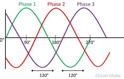
enter image description here

img source: https://circuitglobe.com/wp-content/uploads/2017/03/wave-shape-three-phase-systems.jpg

Let's take a "slice" or an instant of time:
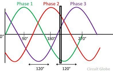
enter image description here

We can represent the current of each phase as a vector with the magnitude representing how much current and the direction representing to or from the load (lets say positive is current to the load and negative is current to the source):
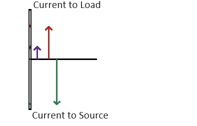
enter image description here

Summing these current vectors amounts to zero net current at this (and all) instants of time:
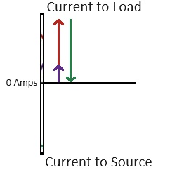
enter image description here

This will be true for any given moment except the differences will be the instantaneous current of each phase. Regardless, Iph_1(t) + Iph_2(t) + Iph_3(t) = 0 Amps which implies no net charge has move to or from the load. Put another way: if the current on phase 2 goes up, the sum of the current of phase 1 + phase 3 has to go down by the same amount to maintain the relationship.

Because the net current through the loop of the ammeter is equals zero, the contribution of of magnetic field of each phase cancels perfectly rendering a reading of 0 amps on your meter.

\$\endgroup\$

Your Answer

By clicking “Post Your Answer”, you agree to our terms of service and acknowledge you have read our privacy policy.

Not the answer you're looking for? Browse other questions tagged or ask your own question.