I've used bootstrapping several times, either to boost the input impedance of an amplifier or to increase its gain. However most of the times I can see the beneficial effects of bootstrapping without actually knowing what's the actual input impedance of an amp due to bootstrapping.
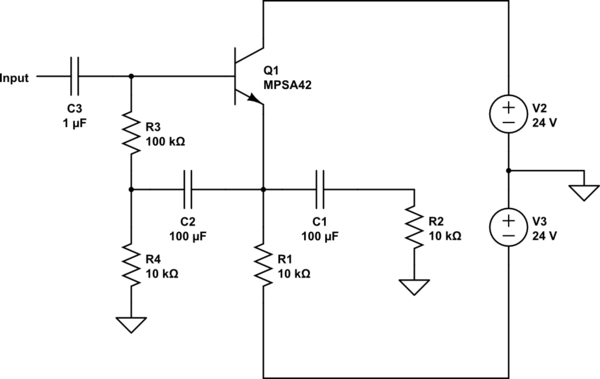
Consider the following emitter follower stage which I got from a textbook.

simulate this circuit – Schematic created using CircuitLab
According to the book from which I got that circuit, the input impedance without the 10kΩ load (\$R_2\$) is 500kΩ and the input impedance with the load is 350kΩ. However the book doesn't provide any formulas or explain how any of those values were derived. So I'm trying to figure it out. This is what I've got:
Just to compare, suppose there is no bootstrap capacitor C2, transistor MPSA42 has a beta of 70, so the input impedance would be roughly \$\beta (R_2\parallel R_1) \parallel R_3\$ (I didn't consider R4 for the calculation since \$R_4 << R_3\$), substituting values results in an input impedance of 77.7kΩ.
Now consider what happens when the bootstrap capacitor is in:
The emitter current of the transistor is approx. \$\frac{24-0.7}{\frac{R_3+R_4}{\beta}+R_1}=2.01mA\$
Which results in an incremental emitter resistor of \$r_e=\frac{V_T}{I_C}=12.93\Omega\$
The voltage gain of the CC stage is roughly:
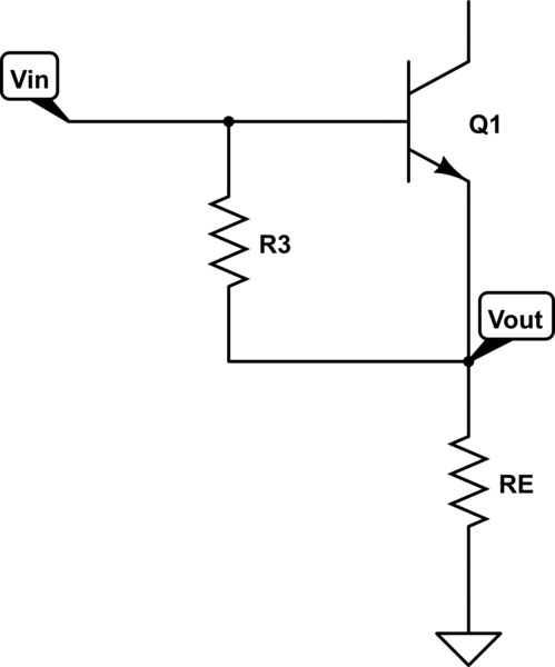
$$A=\frac{R_1 \parallel R_2 \parallel R_4 }{R_1 \parallel R_2 \parallel R_4 +r_e}=0.996$$
Now suppose that 1V is applied to the input. That would mean that the current through \$R_3\$ is \$ \frac{1-0.996}{100k}=40 nA \$ which, compared to the current through the 100kΩ resistor without bootstrap is \$\frac{40nA}{1/100k}=4x10^{-3}\$ times the current without bootstrap. This means the resistance of 100kΩ actually looks like a resistor of \$\frac{1/100k}{40nA}=250\$ times greater value, or \$100k\times 250=25M\Omega\$. This will be in parallel with the resistance reflected from the emitter to the base, which is roughly \$\beta (R_1 \parallel R_2 \parallel R_4)=233k\Omega\$, that in parallel with the 25MΩ resistor gives 230kΩ, as opposed to the 350kΩ mentioned in the book. I checked with a simulator and the input impedance is indeed close to 350kΩ.
What am I doing wrong, is my line of reasoning correct?

