To limit LED current, you can use the following approaches:
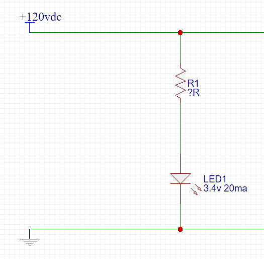
- Use a resistor to limit the current. Since most of the voltage will be dropped by this resistor, most (about 99%) of the power will also be dissipated by the resistor. Since there is no energy storage in the circuit, the dissipation for the entire circuit will be the mains voltage times the chosen LED current.
- Use a capacitor to limit the current. The capacitor will periodically store and release energy, so this circuit has the possibility of being far more efficient. In theory, the LED would be the only dissipating element.
- Use a combination of resistor and capacitor to limit the current. Most of the reason for considering this option will arrive a little later on in the discussion below.
Each of the above possibilities carries with it yet another problem. While the AC mains supply may provide the needed current for the LED in one half of its total cycle time, during the other half the voltage will be arranged so that the LED is reverse-biased. This means the entire mains voltage may be presented across the LED itself. If the LED cannot withstand this voltage well, it may cease to function (and/or explode.)
A simple idea would be to provide a bridge rectifier so that the LED is always forward biased in the circuit. So I'd like to recommend that you consider the addition of a bridge rectifier.
Also, I'd like to recommend that you consider the use of both a capacitor and also a resistor being added to the circuit. The resistor will perform the function of a safety fuse and will add only a very small amount of unwanted dissipation to the circuit. The capacitor will help make the circuit far, far more efficient.
There are special considerations to all elements of the circuit.
Capacitors used for purposes such as these fall into two broad categories:
- Class X -- designed to fail as a short.
- Class Y -- designed to fail as an open.
These each have subcategories, but the most commonly used of each will be X2 and Y2. So we must select from those two distinct categories, I think. (For a web page discussing some of these details, see: Capacitor Class Types, X and Y.)
The choice of which to use depends on what you want to achieve. In this case, since I'm recommending the use of a fusing resistor too, you will want to use a capacitor of the X2 variety that is designed to fail as a short so that the fusing resistor will do its function.
One category of fusing resistors are flame-proof and called "metal oxide film resistors." Some of these have been carefully crafted so that they operate well as fuses, too. ERQA type code from Panasonic and PR01 from Vishay are two examples of such metal film resistors with fusing specifications.
These resistors support the inrush current for a short time, just fine. But will also have a guaranteed value of instantaneous power where they will safely fuse. (Typically, on the order of somewhere between a half-second to a few dozens of seconds duration at some rated instantaneous power rating.)
Panasonic writes something like, "Open within 30 seconds at 12 times the rated power." Vishay provides charts (look on page 12 or so.) Either way, you can use a specification like this to aid a circuit for an LED light attached to the mains system.
Let's say you want to supply approximately \$4\:\text{mA}\$ (RMS) to your LED and your mains power system is \$120\:\text{V}_\text{AC}\$ (RMS).
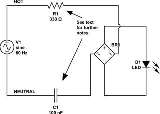
Looking at the above circuit, and ignoring the resistor value for now, we find that the reactance needed (using RMS values) is:
$$X_C=\frac{V_{AC}-V_{LED}-V_{BRIDGE}}{I_{LED}}=\frac{120\:\text{V}-3.4\:\text{V}-2\:\textrm{V}}{4\:\text{mA}}\approx 30\:\text{k}\Omega$$
Or,
$$C=\frac{1}{2\pi\: f\: X_C}=\frac{1}{2\pi\: 60\cdot 30\:\text{k}\Omega}\approx 100\:\text{nF}$$
That's a nice round value and easily picked up.
For the fusing resistor, we are limited by the range of values offered by suppliers. These tend to be values that are \$\le 560\:\Omega\$.
Go to page 12 of the Vishay datasheet and look at the chart on the right side regarding their PR01 types. To be well in the chart here, we need the power (with the capacitor shorted) to be \$30-40\:\text{W}\$ so that we are well within the hatched area. So let's select \$36\:\text{W}\$ as the goal and calculate the resistance as \$\frac{\left(110\:\text{V}\right)^2}{36\:\text{W}}\approx 336\:\Omega\$. A nearby value is \$330\:\Omega\$. So that's the value to select here, as this will guarantee that a capacitor failure will result in this fusing resistor to open up in the circuit.
Oh! Let's look at a schematic:

simulate this circuit – Schematic created using CircuitLab
(Note: Not all systems are handled with one side of the mains power connected to Earth ground -- parts of Japan comes to mind.)
The resistor is placed on the hot side and will disconnect the hot side of the circuit if the capacitor fails short. When the hot side has been disconnected in this way, the capacitor will also hold the entire circuit close to Earth ground, too. Since we are selecting an X2 type of capacitor, it is rated to do just that (if it fails.)
The resistor will normally dissipate under \$10\:\text{mW}\$. So the Vishay offerings regarding PR01 are just fine. You need to make sure you buy a class-X2 rated capacitor. And finally, you need to make sure the bridge supports the voltages present on the AC line. If you build it from diodes, use the 1N4007 types and get the maximum protection (though they are kind of large-bodied.) You may be tempted to use 1N4148 types. And they may work fine in this application. But it's better to get something often used with AC power and designed for the voltages involved. (Take note of the "peak reverse voltage" (PRV) / "peak inverse voltage" (PIV), as this rating needs to be above \$250\:\text{V}\$.)
So there you have it.


