0
\$\begingroup\$

I saw a dimmer on instructables and try to create circuit and pcb for it. However the it looks nice and probably will work but I'm not confident the reliability on long run.
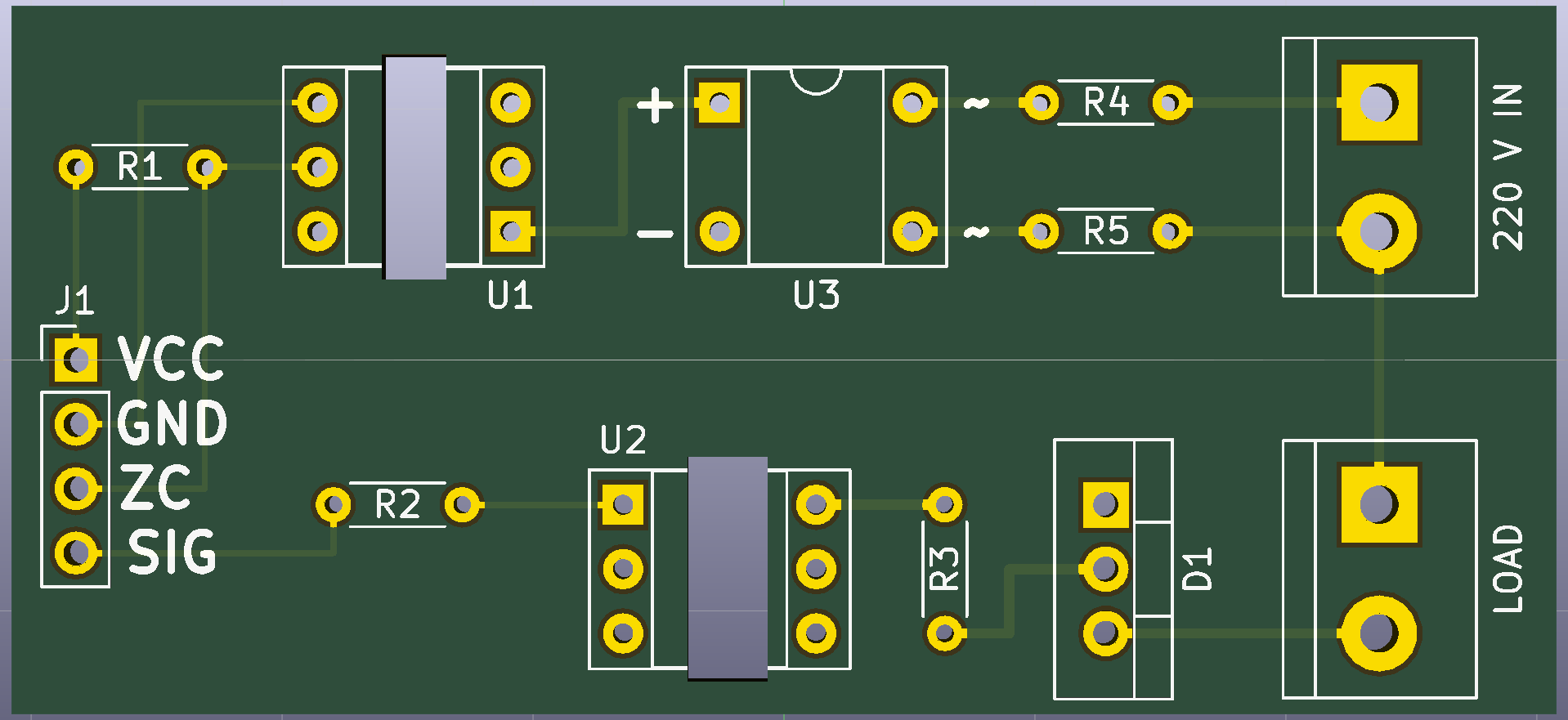
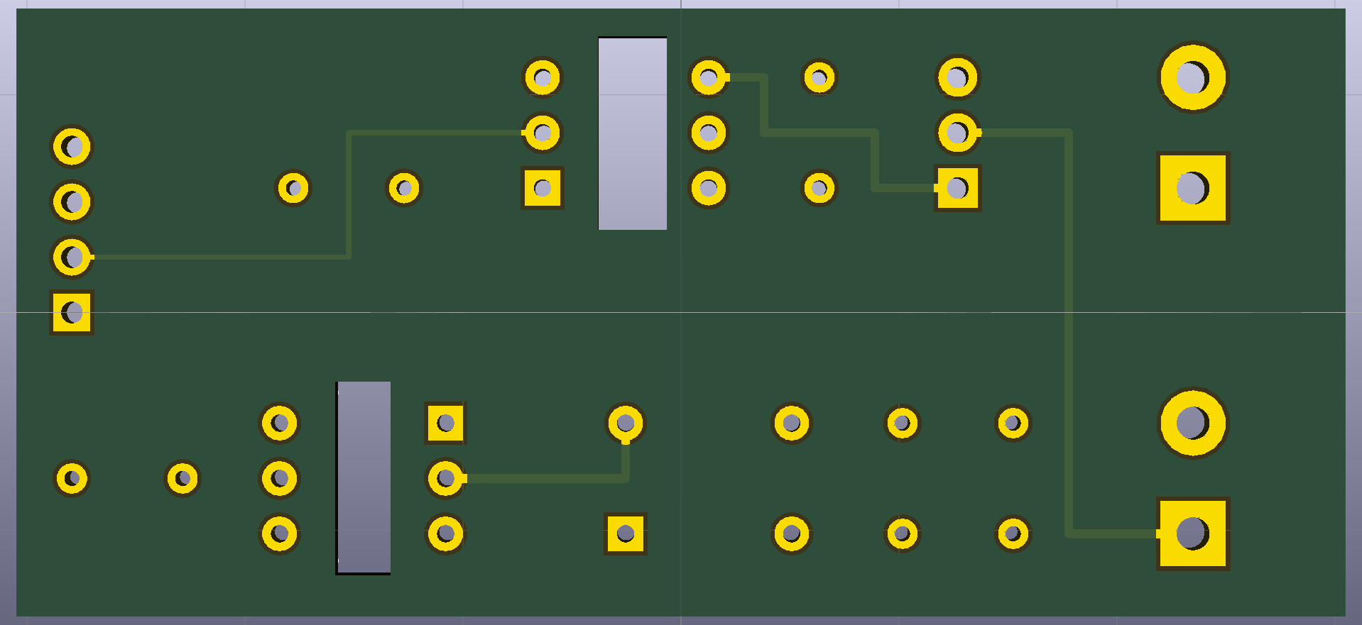
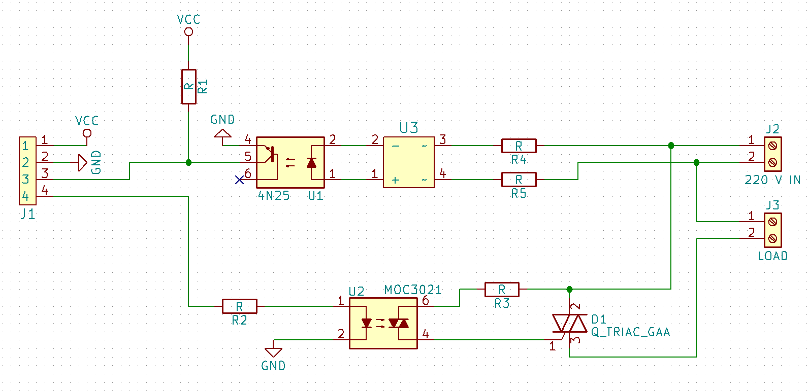
So my question would be if this design violates some safety rules or not. PCB designer PCB front PCB back Schema
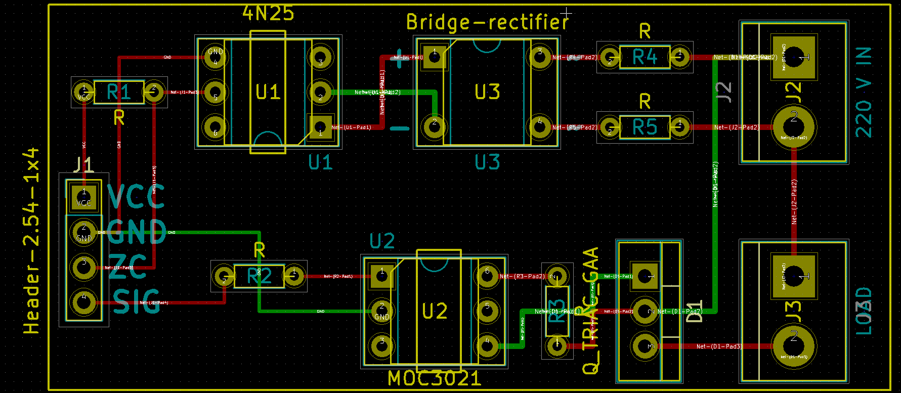
Yes I know the resistors don't have value yet but I still analyzing the datasheets of the optocouplers and the triac I have. (Probably will result more question(s))

\$\endgroup\$
9
  • 2
    \$\begingroup\$ Your mains traces look awful small.. \$\endgroup\$
    – Trevor_G
    Commented Jan 9, 2018 at 18:46
  • 1
    \$\begingroup\$ OK as long as you can guarantee that ;D \$\endgroup\$
    – Trevor_G
    Commented Jan 9, 2018 at 18:55
  • 2
    \$\begingroup\$ YOu could ditch that bridge rectifier if you use an AC optocoupler... google.ca/… \$\endgroup\$
    – Trevor_G
    Commented Jan 9, 2018 at 18:57
  • 1
    \$\begingroup\$ Does your triac have low enough holding current to support 70 mA? \$\endgroup\$
    – winny
    Commented Jan 9, 2018 at 21:21
  • 1
    \$\begingroup\$ @Trevor On the bright side, in the event of a short those traces should act like a fuse :P \$\endgroup\$
    – marcelm
    Commented Jan 9, 2018 at 22:32

1 Answer 1

2
\$\begingroup\$

There is creepage protection for 2.5kV impulse from IEC-664 cat II which requires an air slot gap in case of dust accumulation shown by routed grey zones.

The resistors must be rated for this as well and may need 4 parts for this.

Triacs use REFDES Q1 not D1 and trace width must support any surge current of expected loads.

It is bad practice to have Screen printing between high voltage exposed pads.

\$\endgroup\$
9
  • \$\begingroup\$ So every appliance in my household has to endure 2.5 kV surge? How to determine if a resistor is rated for that? I searched for 2.5kV rated resistors but one of them cost four times than the dimmable led bulb I try to drive and most of them are 150W beasts. -- REFDES -> understood -- You mean that the screen printing spoils the isolation provided by the trace distance? \$\endgroup\$
    – Péter
    Commented Jan 9, 2018 at 19:42
  • 1
    \$\begingroup\$ He never said that, he said your isolation barrier must withstand 2.5 kV peak. PCB cutout is free so if possible line up your optocouplers to make a well defined isolation barrier and make a wide and long cutout. \$\endgroup\$
    – winny
    Commented Jan 9, 2018 at 21:25
  • 1
    \$\begingroup\$ Good eye Trev. This view shows holes in grey with shadows \$\endgroup\$
    – D.A.S.
    Commented Jan 10, 2018 at 0:50
  • 1
    \$\begingroup\$ @Péter it would be better to have the high voltage side and low voltage side divide on the same vertical line on the board.. and suitable silkscreen indication of which side is lethal. (Which is partly why I suggested ditching the bridge rectifier so you can do that) Having them staggered like that can confuse people about what is safe and what is not. Especially when they flip the board over. \$\endgroup\$
    – Trevor_G
    Commented Jan 10, 2018 at 18:48
  • 1
    \$\begingroup\$ As I recall, it depends on the how dirty the intended environment it goes in, ( e.g. high fan dust circulation/accumulation) Often 2.5mm or 0.1" slot is used for low dust areas. \$\endgroup\$
    – D.A.S.
    Commented Jan 11, 2018 at 14:23

Your Answer

By clicking “Post Your Answer”, you agree to our terms of service and acknowledge you have read our privacy policy.

Not the answer you're looking for? Browse other questions tagged or ask your own question.