1
\$\begingroup\$

I'm struggling with the concept of how to schedule my tasks.

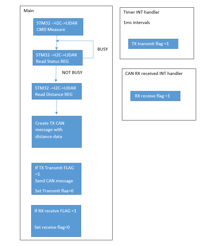
My Setup: STM32F103 hooked up on CAN. Taking measurements with a Lidar V3 module comms via I2C, then distributing that measurement on the CAN

Interrupt 1 is a 1ms timer interrupt to initiate message send on CAN

interrupt 2 is active upon receiving CAN message

I also have to poll a register via I2C on the LIDAR unit to ensure that measurement has finished before I can then use I2C to read the distance register, code snippet shown below

        status = CheckLidarStatus();

        while ((status & LIDAR_BUSY) == LIDAR_BUSY)
        {
            status = CheckLidarStatus();
        }

What I believe is the correct flow that my program should take is shown below:

flow of

My main concerns are:

  1. Does the flow seem a logical way in which to approach this?

  2. If I prioritise the timer interrupt (rather than RX int) for CAN transmission, will this affect the CAN network negatively i.e. not dealing with the received CAN messages promptly enough?

  3. If either of the interrupts are active during I2C comms, will it cause the I2C comms to "fall over"?

  4. Is it acceptable to sit in a while loop waiting for the Checklidar status to come back as not busy, or is there a better way to do this?

\$\endgroup\$
6
  • 2
    \$\begingroup\$ What speed of CAN bus? 1 ms interval is very fast for CAN bus. \$\endgroup\$
    – Jeroen3
    Commented Jan 11, 2018 at 13:58
  • \$\begingroup\$ @Jeroen3 500k baud rate, from my calcs there is 250us Per EXT format frame messsage giving 750us overhead. what would be a more typical update rate for CAN transmission? \$\endgroup\$
    – Pop24
    Commented Jan 11, 2018 at 14:39
  • 2
    \$\begingroup\$ An interval of 100 ms is considered fast. Major standards (eg: j1939) often specify messages must not be repeated within 100 ms. So yeah, 10 ms maybe. But 1 ms, definitely not in a network where you don't control all nodes. \$\endgroup\$
    – Jeroen3
    Commented Jan 11, 2018 at 15:35
  • \$\begingroup\$ @Jeroen3 okay brilliant, thanks for the heads up on that one! \$\endgroup\$
    – Pop24
    Commented Jan 11, 2018 at 15:44
  • \$\begingroup\$ @Jeroen3 10ms is pretty standard. 100ms is trash, you can't use that long delays in a machine control CAN bus. If J1939 specified 100ms intervals, then J1939 should not be used in vehicles. But since it is, I don't believe that 100ms intervals can be mandatory. \$\endgroup\$
    – Lundin
    Commented Jan 18, 2018 at 9:49

2 Answers 2

3
\$\begingroup\$
  1. Yes, it seems logical to me. Although, what's the maximum amount of time that the lidar peripheral could be busy? If that is more than 1 millisecond then you could miss a transmit opportunity. Maybe the busy case should just skip over the data read rather than looping back to poll the status.

  2. Yes, the lower priority interrupt handler will be held off while the higher priority interrupt handler runs. If the higher priority timer interrupt handler runs longer than it takes for the CAN peripheral to receive enough messages to overflow then you would lose messages. That's why it's a good rule of thumb to keep interrupt handlers short. And if all your timer interrupt does is set a flag then I doubt whether you're going to have a problem.

    Another way to consider this is what is the penalty when either interrupt handler is delayed by the other. When the CAN interrupt is delayed by the timer interrupt then you would add lag to CAN response or worst case drop a message. When the timer interrupt is delayed by the CAN interrupt then you would add jitter to the timer interrupt. Worst case would be dropping a millisecond but the CAN interrupt would have to run for more than a millisecond for that to happen. So what is less desirable for your application, a little lag or a little jitter?

  3. It's doubtful that either interrupt would break I2C communications. You're probably using an I2C controller peripheral that transmits/receives bits mostly independently from the CPU. The I2C controller will continue to clock in and out bits as necessary without affect from the interrupts. (If you were bit-banging each bit then there would be more of an impact because individual clocks could get stretched out by an unrelated interrupt. But even that is not necessarily a problem because of the synchronous nature of I2C. The slave device shouldn't care if the I2C clock pulses get stretched out.)

  4. It may be acceptable to poll the lidar status. If you don't have anything else for the CPU to do then what's the harm? But if the lidar peripheral has a "data ready" interrupt of some sort then you could enable that interrupt and wait for the interrupt rather then poll for status.

\$\endgroup\$
4
  • \$\begingroup\$ 1. I will give that a try, skipping over the read distance reg instead of polling the status. It doesnt actually mention what would happen if applying a read command whilst its status is busy, I imagine it would give me the reg value but un updated until measurement has finished. \$\endgroup\$
    – Pop24
    Commented Jan 11, 2018 at 15:17
  • \$\begingroup\$ 2. This is really helpful thanks! 3. yeah its a peripheral, its not the stretching i was worried about, its more the gap between a stop and start point being too big i was concerned with. e.g. to read, i send the address of what i want to read from, then stop I2C. Then I have start I2C again with the address of the device in read mode to recieve the data held in the register. the gap between start and stop was my concern as the data sheet doesnt allude to how quickly this must be done \$\endgroup\$
    – Pop24
    Commented Jan 11, 2018 at 15:27
  • \$\begingroup\$ 4. The lidar is not capabple of generating an interrupt as its connected through I2C, and it doesnt auto generate I2C comms to indicate measurmeent fininshed. However as mention in my first comment you gave me the thought that i can skip checking the status alltogether, and accept that i may read the distance reg more often than it actually updates. the data sheet for the lidar is brief though and does not indicate the reprecussions of reading registers other than status whilst it is busy making a measurement. I think it should be okay though! \$\endgroup\$
    – Pop24
    Commented Jan 11, 2018 at 15:36
  • \$\begingroup\$ Thanks for the answer very helpful and improved my understanding overall!! I think you've given me enough to complete this now. \$\endgroup\$
    – Pop24
    Commented Jan 11, 2018 at 15:36
2
\$\begingroup\$

It is the nature of CAN that when you are trying to send a message, you may experience collisions with higher-priority messages that you need to receive and process.

Your proposal shows extremely simple ISRs that merely set flags, with all of the actual work being done in a single background (non-ISR) thread.

I'm not familiar with the details of the STM32's CAN controller and specifically how autonomous it might be, but your proposal seems inadequate with respect to this issue.

\$\endgroup\$
7
  • \$\begingroup\$ It is autonomous enough that you only have to mark a mailbox ready for transmit. \$\endgroup\$
    – Jeroen3
    Commented Jan 11, 2018 at 13:56
  • \$\begingroup\$ Thanks for your answer, only messages that are meant for this node would require any processing by the processor, which would require taking the data contained and applying it to the lidar via i2c (setttings change to the module). Would you reccomend i put this I2C command in the ISR? \$\endgroup\$
    – Pop24
    Commented Jan 11, 2018 at 15:12
  • 1
    \$\begingroup\$ No, definitely not! The CAN receive ISR should take whatever steps are necessary to make the CAN interface ready to receive the next message, but any other work, such as communicating with the LIDAR, should be deferred to a background thread. \$\endgroup\$
    – Dave Tweed
    Commented Jan 11, 2018 at 15:23
  • 1
    \$\begingroup\$ Somehow, I am not making myself clear. If you need to read data from the CAN controller's FIFO in order to make it ready to receive the next message, then you should definitely do that in the ISR, putting the data into a suitable memory buffer and then setting a flag or whatever for the background thread. However, transmitting that data over the I2C interface takes time, which should NOT be done in the ISR, Instead, the background thread should read the data from the memory buffer and transmit it to the LIDAR at whatever pace is required. \$\endgroup\$
    – Dave Tweed
    Commented Jan 11, 2018 at 16:37
  • 1
    \$\begingroup\$ If I were going to do a project like this, I would have a "thread" devoted just to managing the I2C interface to the LIDAR. It would check for any messages coming from the CAN bus and send them to the LIDAR; otherwise, it would do the polling of the distance data. This makes it easy to manage the contention between the two uses of the I2C interface. \$\endgroup\$
    – Dave Tweed
    Commented Jan 11, 2018 at 16:40

Your Answer

By clicking “Post Your Answer”, you agree to our terms of service and acknowledge you have read our privacy policy.

Not the answer you're looking for? Browse other questions tagged or ask your own question.