0
\$\begingroup\$

I need to design a current amplifier.

I'm sending a PWM signal from 0 to 5V that needs to be converted to 60mA at the maximum (so 5V). I am having trouble figuring out how to design this with either a BJT or MOSFET. I understand how both of them work except for the datasheets are confusing sometimes.

Any help is appreciated

\$\endgroup\$
12
  • \$\begingroup\$ What is the current flowing through? \$\endgroup\$
    – vofa
    Commented Jan 28, 2018 at 1:33
  • \$\begingroup\$ The current from PWM? It is coming from a microcontroller and has not been set yet, it depends on my circuit which I am designing. So technically I can set it to what I want right? I am trying to keep that draw low though. \$\endgroup\$
    – Eric33
    Commented Jan 28, 2018 at 1:39
  • 2
    \$\begingroup\$ I was not clear. What are you trying to push the converted 0-60mA through? \$\endgroup\$
    – vofa
    Commented Jan 28, 2018 at 1:41
  • 1
    \$\begingroup\$ A 100 ohm resistor is a fine, and dependable, voltage-to-current converter. \$\endgroup\$ Commented Jan 28, 2018 at 2:13
  • 2
    \$\begingroup\$ Eric's design team has yet to learn how to write design specs. \$\endgroup\$
    – D.A.S.
    Commented Jan 28, 2018 at 4:07

3 Answers 3

2
\$\begingroup\$

It's not clear why you want to use a transistor for this. Yes, a transistor is an amplifier, but maybe not in the sense you're imagining, hence your confusion when it comes to reading the datasheets.

I will give you the circuit you need to use the transistor in this application. I recommend building it, and then discovering through experimentation why it's not a great choice for this application. Primarily, the amplification ratio (called the "gain") is hard to control in an open loop.
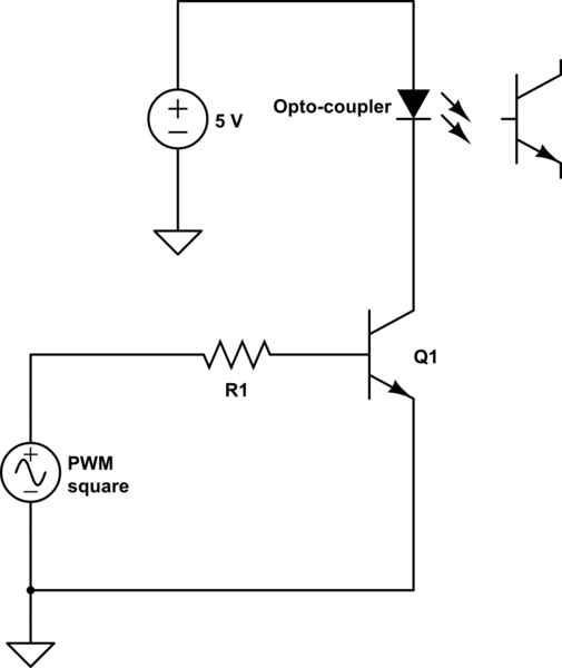
schematic

simulate this circuit – Schematic created using CircuitLab

All you need to do is size R1 such that at 5V, enough base current flows to allow 60mA of collector current to flow. Use these two formulas:

$$ i_b = \frac{5V - 0.7V}{R1} $$ $$ i_c = i_b\beta $$

where \$i_b\$ is the base current, \$5V\$ is the amplitude of the PWM, \$0.7V\$ is the diode drop across the base-emitter junction, \$i_c\$ is the collector current and \$\beta\$ is the BJT gain.

Re-arranging gives:

$$ R1 = \frac{(5V - 0.7V)\beta}{i_c} $$

So say your \$\beta\$ is 100, and your desired \$i_c\$ is 60mA, then \$R1\$ would be about \$7200\Omega\$.

When your PWM duty is 100%, the BJT will allow 60mA to flow. When it is at 50%, it will allow 60mA for 50% of the time, and 0mA for the other 50%, giving an average of 30mA.

In theory at least. In practice you might find it a little wilder than that, at which point you might be tempted to use something like an opamp in a current source topology instead.

\$\endgroup\$
2
  • \$\begingroup\$ +1 for rational thinking. I would add a resistor from base to ground just so base cannot float, or R1 would have to be a very high value. Temp changes will have the beta drift like crazy, but I did mention a servo loop to the OP. Me thinks he will have to work his way up to that level. \$\endgroup\$
    – user105652
    Commented Jan 28, 2018 at 6:55
  • \$\begingroup\$ Ok thank you for the drawing, turns out that I just need a MOSFET.. The optocoupler was not my part of the design so he said he needed 60mA but turns out we need 10mA... We are just going to drive the optocoupler with the PWM signal current. \$\endgroup\$
    – Eric33
    Commented Jan 29, 2018 at 2:34
0
\$\begingroup\$

Buy a 4N33 opto-coupler, or the many that are like it. Drive pin 1 with a 1 K ohm resistor and ground pin 2. Use pin 5 to drive a 2N2222 NPN transistor base to boost the current, as the 4N33 and most opto-couplers cannot handle 60 mA as a load. Pin 3 is not used. Pin 6 sets the gain, but you can leave it open or connect it to pin 4 with a 10 K to 470 K resistor. The higher the value, the more gain the opto-coupler has.

The the 2N2222 emitter is your output, which floats, so you have no ground loops possible. I was going to post a simple design schematic, but the library has no opto-couplers at this time.

If you want precise control then a servo-loop is needed to measure the output current and keep it to a setting of your choice.

\$\endgroup\$
2
  • \$\begingroup\$ The optocoupler is already chosen. I will find out which one it is and post right away, but for now I think we can assume it's low resistance. The design right now has the optocoupler on a different PCB. My PCB receives a PWM signal (0V to 5V) and then sends 0mA to 60mA to another PCB that has the optocoupler on it, then after the optocoupler is ground. \$\endgroup\$
    – Eric33
    Commented Jan 28, 2018 at 3:13
  • \$\begingroup\$ Ok. I should have waited until you posted a schematic first. I may delete my answer if it is of no good. Our answers maybe off track until you supply a schematic or a block diagram. \$\endgroup\$
    – user105652
    Commented Jan 28, 2018 at 4:02
0
\$\begingroup\$

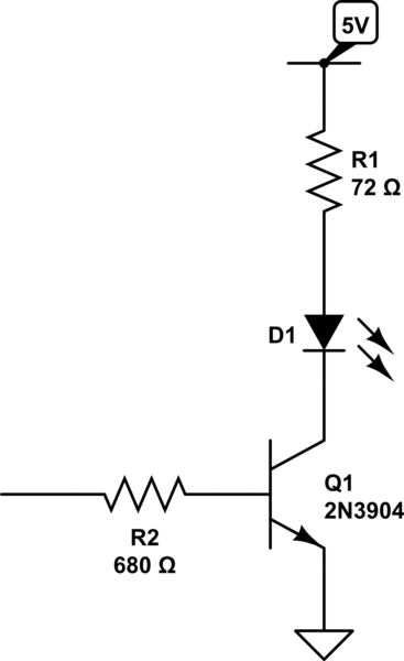
something like this should do it.

schematic

simulate this circuit – Schematic created using CircuitLab

\$\endgroup\$

Your Answer

By clicking “Post Your Answer”, you agree to our terms of service and acknowledge you have read our privacy policy.

Not the answer you're looking for? Browse other questions tagged or ask your own question.