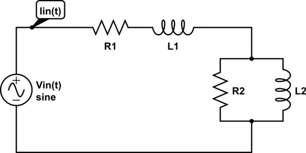
I've the following circuit:

simulate this circuit – Schematic created using CircuitLab
I know that the relation between the input voltage and the input current is given by:
$$\begin{cases} \text{V}_{\space\text{in}}\left(t\right)=\text{I}_{\space\text{in}}\left(t\right)\cdot\text{R}_1+\text{I}_{\space\text{in}}'\left(t\right)\cdot\text{L}_1+\text{V}_{\space\text{R}_2\space||\space\text{L}_2}\left(t\right)\\ \\ \text{I}_{\space\text{in}}'\left(t\right)=\text{V}_{\space\text{R}_2\space||\space\text{L}_2}'\left(t\right)\cdot\frac{1}{\text{R}_2}+\text{V}_{\space\text{R}_2\space||\space\text{L}_2}\left(t\right)\cdot\frac{1}{\text{L}_2} \end{cases}\tag1 $$
Now, when I measure the real input power, I will get an the RMS value of the real input power, and my question is: can I state the following:
$$\text{P}_{\space\text{in RMS}}=\text{P}_{\space\text{R}_1\space\text{RMS}}+\text{P}_{\space\text{R}_2\space\text{RMS}}=\text{I}_{\space\text{in RMS}}^2\cdot\left(\text{R}_1+\text{R}_2\right)\tag2$$
Where:
$$\text{I}_{\space\text{in RMS}}^2=\lim_{\text{n}\to\infty}\sqrt{\frac{1}{\text{n}}\int_0^\text{n}\left(\text{I}_{\space\text{in}}^2\left(t\right)\right)^2\space\text{d}t}=\lim_{\text{n}\to\infty}\sqrt{\frac{1}{\text{n}}\int_0^\text{n}\text{I}_{\space\text{in}}^4\left(t\right)\space\text{d}t}\tag3$$
