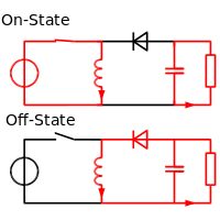
Regarding the inverting BUCK-BOOST shown in figure, I understand how it works as Buck. Please explain how it can act as a BOOST. Because during the off time there is no connection with input supply so i think it cant act as boost. Then why its name as "BUCK-BOOST"
3 Answers
During the on state, the power supply charges the inductor.
During the off state, the supply is disconnected entirely from the inductor. The inductor's energy is delivered into the load, at a voltage determined entirely by the load. Therefore the load voltage can be lower than the input (buck), or higher than the input (boost), it really doesn't matter. The description buck or boost is not really relevant, as the same topology handles voltage increase or decrease.
Ultimately the load voltage is servoed by controlling the power into the load, which is the same (neglecting losses) as controlling the power into the inductor. This is done by controlling the inductor pulse on time, pulse frequency, or both.
-
\$\begingroup\$ One could add the boost feature depends on the load resistance being rather high, making the coil increase the voltage at its terminals accordingly. If that boost is big enough, one could skip the series connection of coil and source present in a "straight" boost converter. \$\endgroup\$– JankaCommented Feb 7, 2018 at 7:17
-
\$\begingroup\$ Please explain. I didnt understand. Within one cycle it can give upto Vin right?. No other series voltage source (voltage in Inductor) like in normal boost converters.. \$\endgroup\$– NandiCommented Feb 7, 2018 at 9:36
-
\$\begingroup\$ within one cycle, it can deliver whatever the output voltage happens to be on the load, ie the load capacitor. If that voltage is low, the current will take a long time to run down in the inductor. If that voltage is high, it will stop quickly. Either way, the same energy that's stored in the inductor gets delivered to the output, and as a result, the voltage on the output cap rises a little. With no load, then for every input pulse, the output voltage rises a little. With a load, and no input pulses, it falls. With a load and pulses, it can be controlled to stay at the right voltage. \$\endgroup\$– Neil_UKCommented Feb 7, 2018 at 12:03
-
1\$\begingroup\$ Upto VIN, it can rise the o/p capacitor voltage right?. We are talking about the one with load and pulse. Inductor voltage can go to high level than supply?. Since there is a load, sufficient current will flow to the load so the o/p cap voltage reduce. So this means inductor only can deliver this?. Then you are saying normal Buck-Converter can act as Boost... \$\endgroup\$– NandiCommented Feb 9, 2018 at 8:58
Because during the off time there is no connection with input supply so i think it cant act as boost.
I think you are concentrating too much on the traditional type of boost converter that has a residual connection to Vin and hence the output voltage is Vin plus the voltage delivered by the inductor energy into the load.
If you redefine what boost means i.e. it can generate a higher output voltage than the input voltage then you should have no problem. After all, you can make a boost converter that generates +100 volts from a +5 volt supply and the fact that 95 of the 100 volts come from the energy storage and conversion process tells you that you shouldn't get too worried about the input voltage propping-up the output voltage by 5%.
-
\$\begingroup\$ // you can make a boost converter that generates +100 volts from a +5 volt supply and the fact that 95 of the 100 volts come from the energy storage // Can you please enlighten me in this case.. My question is if there is no series supply, then how can we boost? You mean the inductor can store voltage more than the supply and it will provide to the load or cap? -- \$\endgroup\$– NandiCommented Feb 9, 2018 at 8:44
-
\$\begingroup\$ @Nandi can you explain, given the answers you have why you don't have an answer to your question? Have you studied the regular boost converter circuit? \$\endgroup\$– Andy akaCommented Feb 9, 2018 at 8:54
-
\$\begingroup\$ I understood the working of normal buck-boost circuits. But in the case of inverting buck-boost its quiet confusing. The normal Boost circuit have the supply voltage in series with the inductor voltage. but for inverting case i dont find anything \$\endgroup\$– NandiCommented Feb 9, 2018 at 9:01
The inverting voltage V = L dI/dt in a repetitive mode is created by the pulsed ON time with the FET, or \$dI=V_cΔt_1/L\$ so the current ramps up with pulse duration when ON.
The switch OFF and Diode conducts with a forward voltage drop at that current and the flyback of the inductor creates a negative voltage. The Capacitor voltage charges the initial current stored in inductor energy \$½LI²=(V_c+V_f)*I*Δt_2\$
Since this is a flyback converter, it does not have separate stages for Buck or Boost, rather this inverting voltage depends is from an impedance ratio from charge to discharge.
To give you an idea of scale, a pulse into an inductor in my cct shown, I = = 250mA 5V*5us/100uH, can results in a discharge voltage pulse of -1kV stored in the cap. when there is no load.
For conversion from +5 to -5V roughly, with ideal parts, a 56% on time for the FET was used here with f= 100kHz, L=100uH, C=5uF, R100 ohm values from -5V the additional boosting effects are created by;
- Reducing L /3 increases Vout = 1.5 * -5V
- Increasing R x2 increases Vout = 1.5 * -5V
- Changing C does not affect Vout except ripple
- Changing the diode affects Vout due to diode losses
- Reducing f /2 increases Vout = 1.5 * -5V
- increasing FET on time by 50% increases (Vout-Vin) x2
