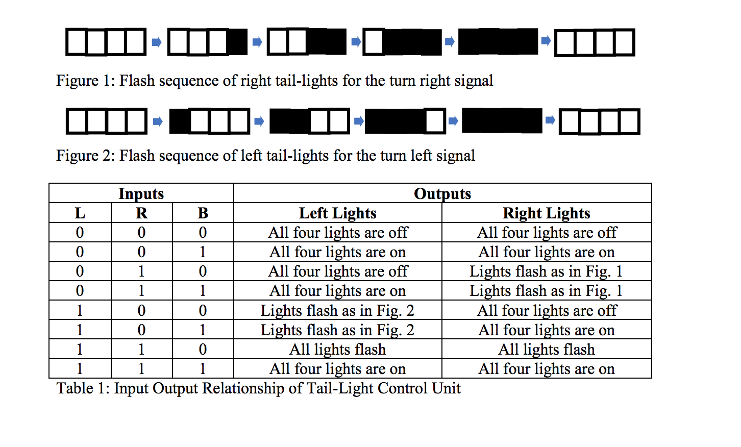
This looks like homework, so I will not give a full answer showing the state arches.
First note that minimum cost has multiple meanings. It can be in terms of:
- Price of the components
- Number of logic gates
- Number of flip-flops or latches
- Number of transistors (may included resistors, capacitors, etc.)
- Some weighted combination of the above
- Sometimes other factors...
The right and left set of tail lights are mirror outputs of each other. Each has only 5 states: All_OFF, OUTERMOST_ON, HALF_ON, INNERMOST_OFF, ALL_ON
Figure out the state diagram for the left or the right (pretend the other side doesn't exist for now). Then figure out the other side. You should notice all you need to do is swap L and R connections; keep the outputs in teams of innermost/outermost (or have bit index mapping to the convention).
It is possible to cover both sets of tail-lights with one 5-state FSM using only 3 flops. This can by done by putting combinational logic between the FSM and final output that can force the output to all-on/all-off. In practice this should not be done on a real vehicle as the output could glitch when input changes. 8-flops (one for each output) is the minimum needed to prevent glitches; plus some possible flops for a counter. This would result in two FSM (may or may-not share a counter if implemented) with identical behavior (different input/output hookup). Automotives likely has additional requirements for safety and reliability.
 I am attempting to implement this tail light design first by using a state diagram. The car has 4 tail lights on each side, making a total of 8. They behave accordingly when the following inputs are implemented.
