0
\$\begingroup\$

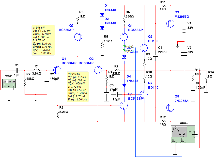
Here is my simple power amplifier:

enter image description here

I need an explanation how the summary DC+AC current will behave on Probe2 and on Probe3 for positive and negative voltage swing of the signal in the amplifier input? How AC part of the amplified signal affects the Q3-Q4 constant current source DC current value? Up yellow box - Probe2, Bottom - Probe 3.

The output graph: red - output, blue - Q6 base

enter image description here

\$\endgroup\$
22
  • \$\begingroup\$ I still think you should use multisim for this and look at the waveforms and present those waveforms that you don't understand so that people can provide help. Also you need to clarify which yellow data box applies to which probe. Is there anything confusing you in the numbers for the yellow boxes? \$\endgroup\$
    – Andy aka
    Commented Feb 14, 2018 at 16:40
  • \$\begingroup\$ @Andy aka I check the yellow boxes, but what waveforms to present for voltage (between probe2 and 3 to ground?) or for current (so I need add resistors to points for probe2 and probe3)? \$\endgroup\$
    – MaxMil
    Commented Feb 14, 2018 at 16:49
  • \$\begingroup\$ Do you know how to run a transient analysis in multisim? \$\endgroup\$
    – Andy aka
    Commented Feb 14, 2018 at 17:12
  • \$\begingroup\$ @Andy aka Yes of course. \$\endgroup\$
    – MaxMil
    Commented Feb 14, 2018 at 17:14
  • \$\begingroup\$ Try probing voltages to produce a transient waveform. I don’t use multisim so I can’t really say much else. \$\endgroup\$
    – Andy aka
    Commented Feb 14, 2018 at 17:14

1 Answer 1

1
\$\begingroup\$

I'm not sure if I understand your question. But I have an idea about it, given the "arrows" I see added to the schematic and added to by your question, which talks about the "positive and negative voltage swing" at the input.

I think you are wondering about what happens to the current source's current as it flows towards and is then sunk by the \$Q_5\$ VAS collector.

In general, if you accept the idea that feedback in the entire amplifier circuit will do what is necessary to ensure that the \$Q_5\$ VAS does the "right job," then the explanation isn't complex. But if you need to walk all the way around the entire closed loop system and look at each detail of how the design, plus feedback, operates on a DC and AC level (the feedback itself has an AC and DC perspective that achieve different things simultaneously), then your question would take more time to answer.

So let me just simplify things for now and ignore a careful discussion of the entire circuit, because I think if you were asking for that perhaps you are asking a far too broad of a question. So I'll assume you just want to know about the current source's current from the source at \$Q_4\$ to the sink at \$Q_5\$.


\$Q_4\$ is, as I think you know, arranged to provide a current source of about \$2\:\text{mA}\$. (Interestingly, this is also the current flowing in the two diodes behind \$Q_4\$ that bias it.) Given the gain in the Sziklai pairs used in both quadrants for the output stage, that may be about right (though I think it is perhaps just a little bit "thin" given the \$33\:\text{V}\$ rails and the power output potential for that.) This current then flows downward towards the \$Q_5\$ collector, where whatever remains is then sunk.

So that's about it, really:

  1. \$2\:\text{mA}\$ is sourced out of \$Q_4\$.
  2. If the upper Sziklai quadrant requires some base drive current for recombination, then this is removed from the \$2\:\text{mA}\$ before it flows through the two diodes towards \$Q_5\$'s collector.
  3. If the lower Sziklai quadrant requires some base drive current for recombination, then this is added to the approximately \$2\:\text{mA}\$ that has now already proceeded through the two diodes on its way towards \$Q_5\$'s collector.
  4. The \$Q_5\$ collector sinks the resulting net current, which will either be a little less than \$2\:\text{mA}\$ (if the upper quadrant required base current) or else a little more than \$2\:\text{mA}\$ (if the lower quadrant required base current) or else very close to \$2\:\text{mA}\$ if the output isn't sourcing or sinking current at the moment.

It's a pretty simple idea.


The whole point of the diff-pair at the input, and the feedback system both at DC (output fed directly back to the diff-pair) and AC (a divided portion fed back), is to cause \$Q_5\$'s collector to do exactly what is needed for the above to work successfully.

\$\endgroup\$
5
  • \$\begingroup\$ Very interesting and useful fo me. You absolutely right and fully understand me when wrote "But if you need to walk all the way around the entire closed loop system...". In first approximation the cosidering of all I need, but when the comments from different authors was added I found that it's not so easy to show all of that. I found that many users do not use that all in their projects. And how do you think is there so granular level really need for practical building of not very complex amplifiers? Or understanding of working principle of simple blocks will be enough? \$\endgroup\$
    – MaxMil
    Commented Feb 15, 2018 at 17:20
  • \$\begingroup\$ @MaxMil The exact details involve a thorough understanding of each subsection of the circuit. But a designer for hobbyist work usually only needs to keep in mind the more important details and knows enough to ignore those that are less important. A commercial product will take a lot more into account and probably will have several different, carefully crafted front end pre-amplifiers targeting minimum noise for a variety of inputs, followed by opamps used in the middle sections, followed by a well-crafted output driver system from discretes. \$\endgroup\$
    – jonk
    Commented Feb 15, 2018 at 17:29
  • \$\begingroup\$ @MaxMil The "level" of thinking required varies. Personally, I don't care about as many of the details that a professional designer of a commercial system will care about. And so I don't worry so much about them for what I might cobble up for personal use. What exactly do you need to know? \$\endgroup\$
    – jonk
    Commented Feb 15, 2018 at 17:35
  • \$\begingroup\$ I want to know is it really need to know all about DC+AC signal components combining in an amplifiers like my or I only need to know about Q-point and that the AC signal modulates the DC Q-point when the signal applied? Is it really need to go deeper for non-professional amplifier construction? \$\endgroup\$
    – MaxMil
    Commented Feb 15, 2018 at 17:40
  • \$\begingroup\$ @MaxMil You go as deep as you want to. Of course, you have to have the basics to start out. Or else you have nothing at all. But once you get the basics, the rest can happen if and when you want to worry more about it. If you want a walk through of your circuit, pose a separate question that specifically asks for an overview level walkthrough of the circuit. This would mean that I would not discuss the details of why a diff-pair works as it does, but I would discuss what it does for you. If that's something that would help. \$\endgroup\$
    – jonk
    Commented Feb 15, 2018 at 18:10

Your Answer

By clicking “Post Your Answer”, you agree to our terms of service and acknowledge you have read our privacy policy.

Not the answer you're looking for? Browse other questions tagged or ask your own question.