0
\$\begingroup\$

How critical is this pull-up resistor to Vdd for current sensing in a Field Oriented Control of a BLDC or PMSM?

enter image description here

Right now, I don't have that pull up...I'm running the shunt resistor voltage straight into the non-inverting pin. Because of this, I'm only getting half-wave rectified current measurements...I'm wondering whether I really need those or not if using SVM modulation. I should also mention that I think what I'm doing is wrong, since I'm unable to get a value for the unmeasured third phase, since for 120 degrees, there is no current flowing from the shunt-resistor phases to ground...So, that's obviously incorrect.

In fact, here's a picture of what my current waveforms look like over a full 360 degree cycle (I'm measuring phase A & B...I'm using KCL to infer phase C):
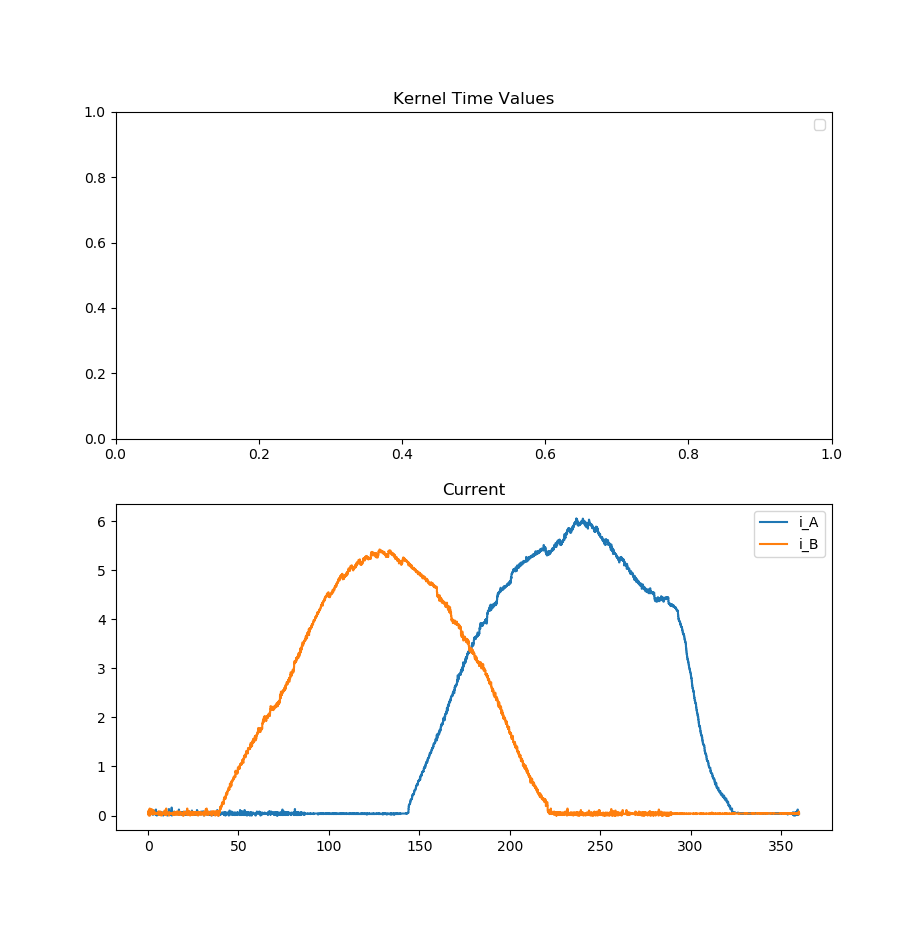
enter image description here. Notice that for the first and last 60 degrees, there is no current in either low side leg...So, leaning on KCL is hopeless and it looks like I'm doing a garbage measurement...

Does this help put 0A at mid-rail or something?

What's the purpose of this? It's not like the current going through any of the legs ever goes below zero in the first place, like in an audio application. Why bother pulling it up to Vdd?

\$\endgroup\$
3
  • \$\begingroup\$ Usually pull-up resistors are used when there is a chance of no input connection or all source current is OFF. They keep the input from 'floating' under such conditions. A floating input is not good, as the device may oscillate in a unstable way. \$\endgroup\$
    – user105652
    Commented Feb 17, 2018 at 23:31
  • \$\begingroup\$ That's true, but that input is pulled to ground through a shunt resistor if there is no current flowing \$\endgroup\$ Commented Feb 17, 2018 at 23:37
  • 1
    \$\begingroup\$ I guess the manufacture is assuming a worst-case scenario, where the shunt resistor opens up due to excessive current flow. With the MOSFETs OFF, the input would float, hence the pull-up resistor. \$\endgroup\$
    – user105652
    Commented Feb 17, 2018 at 23:46

1 Answer 1

1
\$\begingroup\$

The reference side and input side uses this to pull the common mode input into the linear range of most Op Amps.

Otherwise if yours has sensing below ground (Vee) then both pullups to Vin- and Vin+ can be removed.

\$\endgroup\$
2
  • \$\begingroup\$ Does this aid in measuring current flowing from ground into the coil? Because without that pull up, only a half rectified wave could possibly be seen \$\endgroup\$ Commented Feb 18, 2018 at 13:25
  • \$\begingroup\$ Good point .... There must be an offset in the input to permit shifted output to get full wave so if not ground sensing inputs Vin+ needs bigger pullup offsets \$\endgroup\$
    – D.A.S.
    Commented Feb 18, 2018 at 19:06

Your Answer

By clicking “Post Your Answer”, you agree to our terms of service and acknowledge you have read our privacy policy.

Not the answer you're looking for? Browse other questions tagged or ask your own question.