0
\$\begingroup\$

I'm getting an unexpected voltage from a voltage divider I created. Is it likely that the resistor values are too high to provide enough current for my multimeter to measure accurately, or do voltage dividers behave unexpectedly with high resistor values?

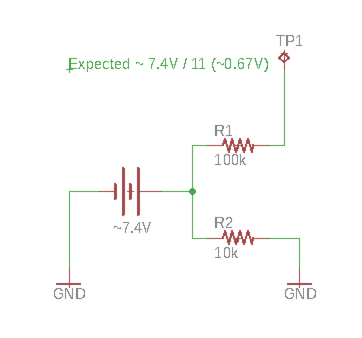
Voltage divider schematic

I'm trying to measure the voltage of the battery but I need to bring the voltage down to below 3.3V as that's all the analogue input of my MCU can tolerate. I created a voltage divider as above. I expected it to reduce the voltage to 1/11 of the battery voltage (~0.67V) but my multimeter is reading 0.35V. I'm wondering if 100K is too high and it's not providing enough current for my multimeter to do it's job. Also interested in any other suggestions. I could reduce the resistor values if that's likely the issue but understood that lower values result in more power consumption.

Thanks!

\$\endgroup\$
0

3 Answers 3

4
\$\begingroup\$

This is not a voltage divider.

Since the applied voltage is between the two resistors the voltage at the top will be the applied voltage assuming nothing is attached to it.

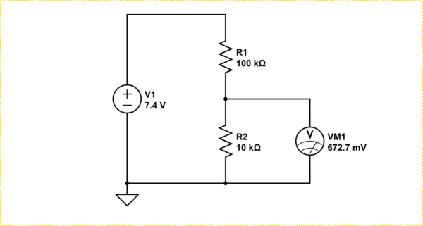
You need to do it this way.

schematic

simulate this circuit – Schematic created using CircuitLab

However, be aware, whatever is attatched where the meter is shown above will affect the voltage to some extent depending on it's resistance. However, I would not expect a typical multimeter to affect it, assuming you do not have it in current measuring mode.

\$\endgroup\$
1
  • 1
    \$\begingroup\$ Thanks Trevor_G and everyone else. Incidentally_your_ diagram describes my actual physical circuit perfectly. I don't know what was going on when I drew the schematic. Aside from the error with my schematic. It sounds like the answer to my question of whether I should expect the multimeter to affect the voltage is probably no. I've also tried with 3 different multimeters since and all give similar results so I think I must have made a mistake with the construction of the circuit or have a faulty resistor. \$\endgroup\$
    – Bruce
    Commented Feb 20, 2018 at 21:09
1
\$\begingroup\$

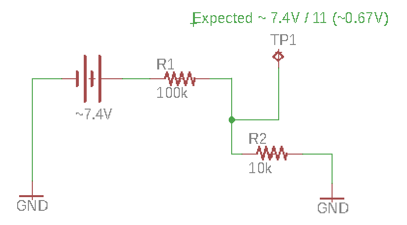
Try this instead.........................: -

enter image description here

\$\endgroup\$
1
  • \$\begingroup\$ Copy cat..LOL. Great cut and paste image editing though ;D \$\endgroup\$
    – Trevor_G
    Commented Feb 20, 2018 at 18:50
0
\$\begingroup\$

As per the previous diagram you have actually created a voltage divider by connecting your meter to the circuit,

Do you know the impedance of your meter , is anyting else connected to your circuit. ?.

\$\endgroup\$
1
  • 1
    \$\begingroup\$ You're going in the wrong direction, I'd call it a goose chase. \$\endgroup\$ Commented Feb 21, 2018 at 3:42

Your Answer

By clicking “Post Your Answer”, you agree to our terms of service and acknowledge you have read our privacy policy.

Not the answer you're looking for? Browse other questions tagged or ask your own question.