7
\$\begingroup\$

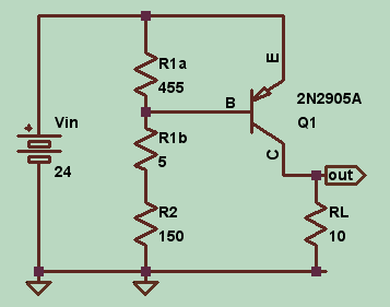
Simple BJT rheostat circuit, with a couple of resistors R1a and R1b representing the two parts of a potentiometer. Simulated in LTSpice IV using a part not suitable for this particular application and current values (I thought I had picked a 2N2955 power transistor, not a 2N2905 small signal transistor) but the problem still stands.

BJT rheostat

The problem is that currents in the transistor operating point do not add up. KCL is blatantly broken with .op (all currents exiting the device, with a large error in Ie - that's more than 6 amps, considering the sign). Please note, the following listing has been slightly edited, but all values are those returned by LTSpice using the default 2N2905A model included in the program.

--- Operating Point ---
V(e):    24         voltage
V(b):    21.6403    voltage
V(out):  22.41      voltage
I(RL):   2.241      device_current

Ic(Q1):  -2.241     device_current
Ie(Q1):  -4.70438   device_current  ???
Ib(Q1):  -0.134429  device_current

I(R2):   0.139615   device_current
I(R1b):  0.139615   device_current
I(R1a):  0.0051861  device_current
I(Vin):  -2.38061   device_current

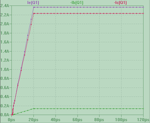
And yet, a .tran simulation (with or without startup directive) gets the currents right as shown here (I made the curves all positive to fit them in the same quadrant).

currents from transient simulation

So, what gives? What is breaking the solver in .op?

EDIT: here's the netlist

Vin E 0 24
R1a E B 455
R2 N001 0 150
R1b B N001 5
Q1 out B E 0 2N2905A
RL out 0 10
.model NPN NPN
.model PNP PNP
.lib I:\Nike\LTSPIC~1\lib\cmp\standard.bjt
.op
.backanno
.end
\$\endgroup\$
9
  • \$\begingroup\$ You have an extra 0 there: Q1 out B E *0* 2N2905A \$\endgroup\$
    – τεκ
    Commented Feb 24, 2018 at 21:48
  • \$\begingroup\$ How did it get there??? Anyhow, I removed it, saved the netlist, run it again: same results. \$\endgroup\$ Commented Feb 24, 2018 at 21:52
  • 2
    \$\begingroup\$ There must be something wrong with the transistor model you have used or with LTspice. Because when I place a small resistor (Rs = 1m ohms) in series with the emitter the LTspice shows I(Rs) = 2.37518A. But Ie is still equal to -4.70351A. Strange. \$\endgroup\$
    – G36
    Commented Feb 24, 2018 at 21:57
  • \$\begingroup\$ @G36 the model is one of the default models offered by LTSpice. But - doh!, I thought I had selected a 2N2955 - 15 amps power transistor, while this is a tiny 2N2905, a 600 mA small signal transistor. So, maybe the fact that in a real circuiti it would have been vaporized has something to do with the error. It still begs the question: why .op is getting it so wrong, while .tran is getting it right? \$\endgroup\$ Commented Feb 24, 2018 at 22:06
  • 1
    \$\begingroup\$ Hmm. Changing the model to 2n2907 the results are sane, but with 2n4403 the problem also occurs. \$\endgroup\$
    – τεκ
    Commented Feb 24, 2018 at 22:08

1 Answer 1

10
\$\begingroup\$

The model is a mess and would take a while to explain why the parameters don't operate together. But it's not just one problem. You can see this from the following two tests.


TEST 1

Try the following model:

.MODEL MYPNP1 ako:2N2905A PNP(NK=1)

And of course use MYPNP1 as your transistor name. See how that behaves in .OP. (All I've done here is to change that parameter from 0.5 to 1.0.)


TEST 2

Try the following model:

.MODEL MYPNP2 ako:2N2905A PNP(RE=.2)

And of course use MYPNP2 as your transistor name. See how that behaves in .OP. (All I've done here is to change the emitter Ohmic resistance from \$0\:\Omega\$ to \$200\:\text{m}\Omega\$.)


Both of the above cases will produce more reasonable results. The fact is, the model is mostly garbage (saturation current is, I think, completely impossible -- but that's only the beginning of it as some of the other parameters that should normally never be 0 are, in fact, 0 in this model.) I don't know why it slipped into LTspice. But it did and I'm not going to try and fix it.

I picked up this model from one of the semiconductor suppliers (Central Semiconductor Corp.):

.MODEL 2N2905A PNP( IS=15.294E-15 BF=297.85 VAF=100 IKF=1.6607 ISE=29.577E-15
+ NE=1.5507 BR=476 VAR=100 IKR=2.2270 ISC=7.6418E-9 NC=2.1591 NK=.97918
+ RB=2.4875 RC=.69253 CJE=33.186E-12 VJE=.8716 MJE=.40799 CJC=15.649E-12
+ VJC=.56868 MJC=.3619 TF=456.18E-12 XTF=22.393 VTF=28.493 ITF=.62109
+ TR=10.000E-9 )

At least it appears to run okay with .OP.


I guess a lesson here is that it's possible to write BJT models that will produce crazy results in .OP, while producing more normal DC results in .TRAN. This is actually the more interesting aspect of this problem to me. I can't recall seeing that before.

\$\endgroup\$
1
  • 1
    \$\begingroup\$ Yep, after I realized I had used a tiny 2905 instead of a beefy 2955, I re-ran the simulation with a 2955 model taken from LTwiki and all went fine. While I can understand that using a part unsuitable for the job could cause problems, like you I find most interesting the fact that one solver is getting it right, while the other is missing nearly 7 amps of current. I wonder if they went to GND through the hidden substrate terminal (used perhaps by .op and not by .tran). \$\endgroup\$ Commented Feb 25, 2018 at 0:51

Your Answer

By clicking “Post Your Answer”, you agree to our terms of service and acknowledge you have read our privacy policy.

Not the answer you're looking for? Browse other questions tagged or ask your own question.