1
\$\begingroup\$

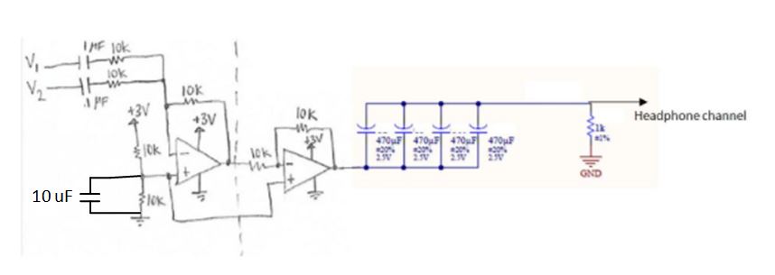
I made a simple audio mixer circuit with its output going to headphones. Right now I'm only testing with a single audio signal at the input, which is music from a smartphone. I hear a pop sound after I apply power (2 x AA) to the circuit, unless power has already been applied for at least approximately five seconds. Even if I leave power applied for a minute, and then I disconnect and reconnect power, there is a pop sound. What about this circuit would take five seconds to stabilize? VCC stabilized nearly instantly when I measured on the scope.

enter image description here

I'm using a dual op amp IC, the LM4808 (http://www.ti.com/lit/ds/symlink/lm4808.pdf).

There are four 470 uF decoupling caps in parallel at the output (for a desired cutoff), and a 1k resistor to Ground that I included as a discharge resistor, but it doesn't seem to have any effect.

\$\endgroup\$
6
  • \$\begingroup\$ You have at least 3 places where the residual charges may be adequate to cause popping. \$\endgroup\$ Commented Feb 27, 2018 at 2:59
  • \$\begingroup\$ Where? Why would it take that long? \$\endgroup\$
    – donut
    Commented Feb 27, 2018 at 3:02
  • \$\begingroup\$ In most cases a single 470 uF cap at the output is enough. Unless you have 32 bit audio with bass down to 2 HZ, in which case this circuit would not be good enough. \$\endgroup\$
    – user105652
    Commented Feb 27, 2018 at 3:37
  • \$\begingroup\$ Please keep your "answers" to yourself or post them where they belong. As you can see, because of these non-answers, OP is already trying to initiate a discussion in the comment thread. They are not "helpful" to this website. \$\endgroup\$
    – pipe
    Commented Feb 27, 2018 at 3:38
  • 1
    \$\begingroup\$ Read: Pop & Click in Audio Amplifiers and I think you will immediately see the discussion on page 2 striking directly into the heart of at least one problem you have. \$\endgroup\$
    – jonk
    Commented Feb 27, 2018 at 4:22

3 Answers 3

1
\$\begingroup\$

Here's what the data sheet says about Cb (the 10 uF capacitor in your circuit): -

Bypass Capacitor Value

Besides minimizing the input capacitor size, careful consideration should be paid to the value of the bypass capacitor, CB. Since CB determines how fast the LM4808 settles to quiescent operation, its value is critical when minimizing turn-on pops. The slower the LM4808's outputs ramp to their quiescent DC voltage (nominally 1/2 VDD), the smaller the turn-on pop. Choosing CB equal to 1.0μF or larger, will minimize turn-on pops. As discussed above, choosing Ci no larger than necessary for the desired bandwidth helps minimize clicks and pops.

So I would definitely experiment with this value and initially try 1 uF. Also, it makes little sense to use both amplifiers (not op-amps BTW) of this package - attach your headphone decoupling capacitors to the first stage. Cascading two stages might make the popping problem worse.

You should also note that having nearly 2000 uF coupling your headphones (32 ohms or thereabouts) has a high pas cut-off of only 2.5 Hz and this is too low for audio. Make it more like 220 uF and you might find the pop is reduced.

\$\endgroup\$
5
  • \$\begingroup\$ A slower ramp up allows more time for the output capacitor to charge up, thus reducing the 'pop'. But when the output capacitor is far larger than necessary... \$\endgroup\$ Commented Feb 27, 2018 at 9:27
  • \$\begingroup\$ Ok I'll try 1 uF, but I'm not sure why it should theoretically work based on the datasheet because it says "1 uF or larger" and this capacitor "determines how fast the LM4808 settles to quiescent operation", so it would be a slower ramp up to the quiescent DC voltage if I'm using 10 uF. I don't understand the consequence of using a larger cap here. I'm cascading two op amps in order to de-invert the output from the first stage (it's just a requirement for my application). Why would you put decoupling caps at the output of the first stage? In addition to the second stage? \$\endgroup\$
    – donut
    Commented Feb 27, 2018 at 18:03
  • \$\begingroup\$ I'm suggesting you only use 1 stage and forget about the 2nd stage. Also use smaller capacitiance for the headphone such as 220 uF. You don't need any more than that. \$\endgroup\$
    – Andy aka
    Commented Feb 27, 2018 at 18:10
  • \$\begingroup\$ I have to use the second stage in order to de-invert the output from the first inverting summing amplifier stage. Is it a problem to not have an input capacitance to the second stage? Should there be a 1 uF input capacitor like in the first stage? ...I need a large capacitance at the output because it needs to work with very low impedance headphones with around 10 ohms nominal impedance, for a 10 Hz cut off. \$\endgroup\$
    – donut
    Commented Feb 27, 2018 at 18:37
  • \$\begingroup\$ @donut why not use a non-inverting summing amplifier? \$\endgroup\$
    – BeB00
    Commented Jul 20, 2019 at 21:12
0
\$\begingroup\$

The RC time constant of your output stage is \$\tau=4*470\mu F * 1k = 1.88s\$, and it takes 5 time constants for the voltage to be 99% of the steady state voltage. Basically, the pop happens because it takes a couple of time constants for the output capacitor to charge up to the DC voltage of the output stage, such that when you reapply power there is no (noticeable) sharp transition.

\$\endgroup\$
7
  • \$\begingroup\$ The headphones are an impedance in parallel with the 1k resistor, and they have a nominal impedance of 32 ohms, so wouldn't that make the time constant only 0.058s? \$\endgroup\$
    – donut
    Commented Feb 27, 2018 at 3:38
  • \$\begingroup\$ Hmm, yeah I guess so. \$\endgroup\$
    – C_Elegans
    Commented Feb 27, 2018 at 3:56
  • \$\begingroup\$ ... and it is the sudden current through the headphones that is causing the pop. \$\endgroup\$
    – Transistor
    Commented Feb 27, 2018 at 7:14
  • \$\begingroup\$ Shouldn't the discharge resistor prevent that problem? \$\endgroup\$
    – donut
    Commented Feb 27, 2018 at 7:53
  • \$\begingroup\$ Also, there is no popping when I wait at least five seconds after applying power, and then connect headphones to the amplifier output. \$\endgroup\$
    – donut
    Commented Feb 27, 2018 at 8:05
0
\$\begingroup\$

Shouldn't the discharge resistor prevent that problem?

No. The discharge resistor is part of the problem.

there is no popping when I wait at least five seconds after applying power, and then connect headphones to the amplifier output.

That confirms what is happening. The output capacitors are charging up through the (unknown reference designator) resistor.

When power is applied, there is zero charge on the output caps. The opamp output snaps up to Vcc/2 volts, and now the caps start to charge up to this value through the resistor. If you put a scope across the resistor, you will see a voltage spike with an exponential decay. Connecting the phones shortens the decay time, but now some of the charging current is going through the earphone coil, causing the diaphragm to jump, producing an audible pop.

Decreasing the cap array value will decrease the amplitude of the pop, but not eliminate it. But if you want flat response down to x Hz, the output stage corner frequency should be x/2 Hz for a 1 dB voltage drop and tolerable phase shift, and x/10 Hz for "clean" audio.

High power audio amplifiers have a speaker disconnect relay driven by a time delay circuit to prevent potentially speaker-damaging pops on power up. While those amps usually have a bipolar power system that eliminates the output coupling capacitor, there is no guarantee that the two supplies will come up perfectly symmetrically, causing an output pop for a different reason.

\$\endgroup\$

Your Answer

By clicking “Post Your Answer”, you agree to our terms of service and acknowledge you have read our privacy policy.

Not the answer you're looking for? Browse other questions tagged or ask your own question.