1
\$\begingroup\$

I'm trying to use the Segger JLINK edu mini( https://www.segger.com/products/debug-probes/j-link/models/j-link-edu-mini/ ) to program a board that is also powered by USB. It has a pin out shown on the page linked above and also comes with a 20 pin cable suggesting it can do all the things a 20 pin SWD connector can do including power 5V from USB. The little USB stick itself has only a 10 pin connector.

What I'd like to do, is get 5V out of the Jlink edu mini to power my board. My VTREF is 3.3V but it needs input power from somewhere. The 20 pin JTAG pin out does this - I am wondering is there a way to output 5V using this smaller 10 pin connector and if anyone has run into this problem?

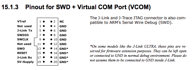
This is the 20 pin connector pin out which includes a 5V power source

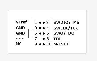
This is the Segger Jlink Edu mini 10 pin out which does not have the 5V - is there a way to convert one to the other?

\$\endgroup\$

1 Answer 1

2
\$\begingroup\$

Programmers by defaults do not supply power. It only uses some target power. This way the programmer can be used for all logic levels, eg: 1.8V, 3.3 and 5V.

However, Segger does have 5V-Supply pin.

Pins 11 and 13 of the connector can be used to supply power to the target hardware. Supply voltage is 5V, max. current is 300mA. The output current is monitored and protected against overload and short-circuit. Power can be controlled via the J-Link commander.

But you'll have to turn it on by software.

If 5V is too much, you can get an power supply adapter. (little board with linear regulator)

If you want power on some other pin, you'll have to change the pin-out of the programming header using a converter board.

\$\endgroup\$

Your Answer

By clicking “Post Your Answer”, you agree to our terms of service and acknowledge you have read our privacy policy.

Not the answer you're looking for? Browse other questions tagged or ask your own question.